|
поискавой системы для электроныых деталей |
|
|
поискавой системы для электроныых деталей |
|
ADP1053ACPZ-R7 датащи(PDF) 50 Page - Analog Devices |
|
|
|||||||||||||||||||||||||||||
ADP1053ACPZ-R7 датащи(HTML) 50 Page - Analog Devices |
|
|
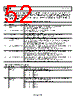
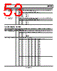
50 / 84 page  ADP1053 Data Sheet Rev. A | Page 50 of 84 MANUFACTURER-SPECIFIC EXTENDED COMMAND REGISTER DESCRIPTIONS FLAG CONFIGURATION REGISTERS Register 0xFE00 to Register 0xFE05 and Bits[3:0] of Register 0xFE06 are used to set the flag response and the resolution after the flag is cleared. Bits[7:6] of Register 0xFE06 set the global flag reenable delay time. Table 30. Register 0xFE00 to Register 0xFE06—Flag Configuration Registers Registers Bits Flag Other Flag Configuration Registers Flag Registers (Read-Only Status Registers) 0xFE00 [7:4] CS1_B_OCP 0xFE71 0xFEC1, 0xFEC6 0xFE00 [3:0] CS1_A_OCP 0xFE70 0xFEC0, 0xFEC5 0xFE01 [7:4] CS2_B_OCP 0xFE19 0xFEC1, 0xFEC6 0xFE01 [3:0] CS2_A_OCP 0xFE18 0xFEC0, 0xFEC5 0xFE02 [7:4] OVP_B 0xFE27 0xFEC1, 0xFEC6 0xFE02 [3:0] OVP_A 0xFE26 0xFEC0, 0xFEC5 0xFE03 [7:4] UVP_B 0xFE29 0xFEC1, 0xFEC6 0xFE03 [3:0] UVP_A 0xFE28 0xFEC0, 0xFEC5 0xFE04 [7:4] ACSNS 0xFE78 0xFEC2, 0xFEC7 0xFE04 [3:0] CS_OCP 0xFE6F 0xFEC2, 0xFEC7 0xFE05 [7:4] OTP2 0xFE76 0xFEC2, 0xFEC7 0xFE05 [3:0] OTP1 0xFE75 0xFEC2, 0xFEC7 0xFE06 [3:0] FLAGIN 0xFE0F 0xFEC2, 0xFEC7 Table 31. Register 0xFE00 to Register 0xFE05—Flag Configuration Register Bit Descriptions Bits Bit Name R/W Description These bits specify the action to take when the flag is set. Bit 7 Bit 6 Flag Action 0 0 None 0 1 Disable PWM outputs in Channel A 1 0 Disable PWM outputs in Channel B [7:6] Flag action R/W 1 1 Disable all PWM outputs (Channel A, Channel B, and Channel C) R/W These bits specify the action to take after the flag is cleared. Bit 5 Bit 4 Action After Flag Is Cleared 0 0 After the reenable delay time, the PWM outputs are reenabled using the soft start process 0 1 The PWM outputs are reenabled immediately without a soft start 1 0 A PSON signal is needed to reenable the PWM outputs [5:4] Action after flag is cleared 1 1 A PSON signal is needed to reenable the PWM outputs [3:2] Flag action R/W These bits specify the action to take when the flag is set. Bit 3 Bit 2 Flag Action 0 0 None 0 1 Disable PWM outputs in Channel A 1 0 Disable PWM outputs in Channel B 1 1 Disable all PWM outputs (Channel A, Channel B, and Channel C) R/W These bits specify the action to take after the flag is cleared. Bit 1 Bit 0 Action After Flag Is Cleared 0 0 After the reenable delay time, the PWM outputs are reenabled using the soft start process 0 1 The PWM outputs are reenabled immediately without a soft start 1 0 A PSON signal is needed to reenable the PWM outputs [1:0] Action after flag is cleared 1 1 A PSON signal is needed to reenable the PWM outputs |
|
ссылки URL |
| Вашему бизинису помогли Аллдатащит? [ DONATE ] |
Что такое Аллдатащит | реклама | контакт | Конфиденциальность | Ссылка на техническое описание | обмен ссыками | поиск по производителю All Rights Reserved©Alldatasheet.com |
| Russian : Alldatasheetru.com | Korean : Alldatasheet.co.kr | Spanish : Alldatasheet.es | French : Alldatasheet.fr | Italian : Alldatasheetit.com Portuguese : Alldatasheetpt.com | Polish : Alldatasheet.pl | Vietnamese : Alldatasheet.vn Indian : Alldatasheet.in | Mexican : Alldatasheet.com.mx | British : Alldatasheet.co.uk | New Zealand : Alldatasheet.co.nz |
|
Family Site : ic2ic.com |
icmetro.com |
 Russian ▼
 English
 Chinese
 German
 Japanese
 Russian
 Korean
 Spanish
 French
 Italian
 Portuguese
 Polish
 Vietnamese
 Indian
 Mexican
 British
 New Zealand