|
поискавой системы для электроныых деталей |
|
|
поискавой системы для электроныых деталей |
|
ADP1053ACPZ-R7 датащи(PDF) 34 Page - Analog Devices |
|
|
|||||||||||||||||||||||||||||
ADP1053ACPZ-R7 датащи(HTML) 34 Page - Analog Devices |
|
|
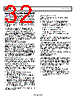
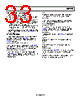
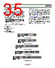
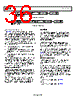
34 / 84 page  ADP1053 Data Sheet Rev. A | Page 34 of 84 PMBus/I2C COMMUNICATION The PMBus slave allows a device to interface to a PMBus- compliant master device, as specified by the PMBus Power System Management Protocol Specification (Revision 1.1, February 5, 2007). The PMBus slave is a 2-wire interface that can be used to communicate with other PMBus-compliant devices and is compatible in a multimaster, multislave bus configuration. FEATURES The function of the PMBus slave is to decode the command sent from the master device and respond as requested. Communi- cation is established using an I2C-like 2-wire interface with a clock line (SCL) and data line (SDA). The PMBus slave is designed to externally move chunks of 8-bit data (bytes) while maintaining compliance with the PMBus protocol. The PMBus protocol is based on the SMBus Specification (Version 2.0, August 2000). The SMBus specification is, in turn, based on the Philips I2C Bus Specification (Version 2.1, January 2000). The PMBus incorporates the following features: • Slave operation on multiple device systems • 7-bit addressing • 100 kHz and 400 kHz data rates • General call address support • Support for clock low extension (clock stretching) • Separate multibyte receive and transmit FIFO • Extensive fault monitoring OVERVIEW The PMBus slave module is a 2-wire interface that can be used to communicate with other PMBus-compliant devices. Its trans- fer protocol is based on the Philips I2C transfer mechanism. The ADP1053 is always configured as a slave device in the overall system. The ADP1053 communicates with the master device using one data pin (SDA) and one clock pin (SCL). Because the ADP1053 is a slave device, it cannot generate the clock signal. However, it is capable of clock-stretching the SCL line to put the master device in a wait state when it is not ready to respond to the master’s request. Communication is initiated when the master device sends a command to the PMBus slave device. Commands can be read or write commands, in which case data is transferred between the devices in a byte wide format. Commands can also be send commands, in which case the command is executed by the slave device upon receiving the stop bit. The stop bit is the last bit in a complete data transfer, as defined in the PMBus/I2C communi- cation protocol. During communication, the master and slave devices send acknowledge (A) or not-acknowledge (A) bits as a method of handshaking between devices. See the PMBus speci- fication for a more detailed description of the communication protocol. When communicating with the master device, it is possible for illegal or corrupted data to be received by the PMBus slave device. In this case, the PMBus slave device should respond to the invalid command or data, as defined by the PMBus specifi- cation, and indicate to the master device that an error or fault condition has occurred. This method of handshaking can be used as a first level of defense against inadvertent programming of the slave device that can potentially damage the chip or system. The PMBus specification defines a set of generic PMBus commands that is recommended for a power management system. However, each PMBus device manufacturer can choose to implement and support certain commands as it deems fit for its system. In addition, the PMBus device manufacturer can choose to implement manufacturer-specific commands whose functions are not included in the generic PMBus command set. The list of standard PMBus and manufacturer-specific commands can be found in the PMBUS Command Set (Supported by the ADP1053) section and the Manufacturer-Specific Extended Command List section. PMBus/I2C ADDRESS The PMBus address of the ADP1053 is set by connecting an external resistor from the ADD pin to AGND. Table 11 lists the recommended resistor values and associated PMBus addresses. Seven different addresses can be used. Table 11. PMBus Address Settings and Resistor Values PMBus Address ADD Pin Resistor Value (kΩ) 0x60 10 (or connect directly to AGND) 0x61 28.7 0x62 48.7 0x63 68.1 0x64 88.7 0x65 109 0x67 200 (or connect directly to VDD) The recommended resistor values in Table 11 can vary by ±2 kΩ. Therefore, it is recommended that 1% tolerance resistors be used on the ADD pin. The part responds to the standard PMBus broadcast address (general call) of 0x00. However, it is not recommended that the general call address be used when more than one ADP1053 is connected to the master device because the data returned by multiple slave devices will be corrupted. For more information, see the General Call Support section. |
|
ссылки URL |
| Вашему бизинису помогли Аллдатащит? [ DONATE ] |
Что такое Аллдатащит | реклама | контакт | Конфиденциальность | Ссылка на техническое описание | обмен ссыками | поиск по производителю All Rights Reserved©Alldatasheet.com |
| Russian : Alldatasheetru.com | Korean : Alldatasheet.co.kr | Spanish : Alldatasheet.es | French : Alldatasheet.fr | Italian : Alldatasheetit.com Portuguese : Alldatasheetpt.com | Polish : Alldatasheet.pl | Vietnamese : Alldatasheet.vn Indian : Alldatasheet.in | Mexican : Alldatasheet.com.mx | British : Alldatasheet.co.uk | New Zealand : Alldatasheet.co.nz |
|
Family Site : ic2ic.com |
icmetro.com |
 Russian ▼
 English
 Chinese
 German
 Japanese
 Russian
 Korean
 Spanish
 French
 Italian
 Portuguese
 Polish
 Vietnamese
 Indian
 Mexican
 British
 New Zealand