|
поискавой системы для электроныых деталей |
|
|
поискавой системы для электроныых деталей |
|
USB97C102 датащи(PDF) 57 Page - SMSC Corporation |
|
|
|||||||||||||||||||||||||||||
USB97C102 датащи(HTML) 57 Page - SMSC Corporation |
|
|
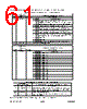
57 / 80 page  SMSC DS – USB97C102 Page 57 Rev. 03/23/2000 Table 103 - SIE Status Register SIE_STAT (0x7F93 - RESET=0x03) SIE STATUS REGISTER BIT NAME R/W DESCRIPTION 7 ERR R Indicates that an error occurred during the last USB transaction. Considered valid on the rising edge of EOT 6 TIMEOUT R Indicate that the last USB transaction ended because of an inter-packet time out condition (i.e.:>16 bit times). Considered valid on the rising edge of EOT. 5 SETUP_TOKEN R Indicates that the token received was a SETUP token. 4 SOF_TOKEN R Indicates that the SOF PID has been received. Considered valid when EOT is '0'. 3 PRE_TOKEN R Indicates that the SIE detected a PRE (preamble) packet on the USB bus. The signal is asserted when the SIE has seen a valid SYNC followed by a valid PRE PID. 2 ACK R Indicates that the last USB transaction was completed without error or time-out. Considered valid on the rising edge of EOT. 1 USB_RESET R When active '1', it indicates that the USB line is being reset. This signal is asserted when the SIE detects a string of single – ended 0's on the bus for a long time. [During USB_RESET, this bit is set(1). When the firmware sends a system reset, this bit is cleared(0)] 0 EOT R End - of - Transaction. On transition to a '1', it indicates the end of transaction. On transition to a '0' it indicates the beginning of a new transaction. Note: This read only register reflects the status signals from the SIE state machine. This register can be polled for test purposes, or by error handling routines for recovery. Table 104 - SIE Control Register 1 SIE_CTRL1 (0x7F94 - RESET=0x00) SIE CONTROL REGISTER 1 BIT NAME R/W DESCRIPTION 7 SIEDMA_DISABLE R/W 0 = Normal operation 1 = Inhibits SIEDMA operation to facilitate MCU override 6 FORCE_RXOK R/W Forces SIE to send Acknowledge during receive. Must be '0' for normal operation. 5 FORCE_TTAG R/W 0 = Normal operation 1 = Signals that the next byte written to the SIE TX_FIFO is the last payload byte. 4 FORCE_RXOVFLO R/W 0 = Normal operation. 1 = Forces the SIE to generate RXOVFLO and clear the SIE RX FIFO. 3 FORCE_TXABORT R/W 0 = Normal operation 1 = Forces a bit-stuff error at the host 2 FORCE_EOT R/W 0 = Normal operation 1 = Forces an End-of-Transaction for the SIE 1 RTAG_IN R Status of RTAG signal from SIE RX FIFO 0 TXOK_IN R Status of TXOK from SIE Note: Bits 7:2 must be set to “0” for normal operation. Altering these bits will cause an abnormal USB behavior. |
|
ссылки URL |
| Вашему бизинису помогли Аллдатащит? [ DONATE ] |
Что такое Аллдатащит | реклама | контакт | Конфиденциальность | Ссылка на техническое описание | обмен ссыками | поиск по производителю All Rights Reserved©Alldatasheet.com |
| Russian : Alldatasheetru.com | Korean : Alldatasheet.co.kr | Spanish : Alldatasheet.es | French : Alldatasheet.fr | Italian : Alldatasheetit.com Portuguese : Alldatasheetpt.com | Polish : Alldatasheet.pl | Vietnamese : Alldatasheet.vn Indian : Alldatasheet.in | Mexican : Alldatasheet.com.mx | British : Alldatasheet.co.uk | New Zealand : Alldatasheet.co.nz |
|
Family Site : ic2ic.com |
icmetro.com |
 Russian ▼
 English
 Chinese
 German
 Japanese
 Russian
 Korean
 Spanish
 French
 Italian
 Portuguese
 Polish
 Vietnamese
 Indian
 Mexican
 British
 New Zealand