|
поискавой системы для электроныых деталей |
|
|
поискавой системы для электроныых деталей |
|
ADP1055ACPZ-R7 датащи(PDF) 114 Page - Analog Devices |
|
|
|||||||||||||||||||||||||||||
ADP1055ACPZ-R7 датащи(HTML) 114 Page - Analog Devices |
|
|
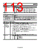
114 / 140 page  ADP1055 Data Sheet Rev. A | Page 114 of 140 Table 193. Register 0xFE50—PULSE_SKIP_AND_SHUTDOWN Bits Bit Name R/W Description [7:6] Addition PS on time after end of soft stop ramp R/W To allow any negative current to dissipate, PWM outputs such as the SR outputs are kept active after the soft stop ramp-down. Bit 7 Bit 6 LSBs 0 0 No additional on time at the end of soft stop. All PWM outputs are shut off immediately at end of ramp. The SR PWM outputs continue to increase their modulation limit and completely turn on for the entire switching cycle after the maximum limit is reached. 0 1 2 ms of extra on time. 1 0 4 ms of extra on time. 1 1 8 ms of extra on time. 5 Instant SR transition R/W 1 = SR outputs move from LLM to normal mode instantly. 0 = SR outputs transition from one mode to another (LLM to CCM or CCM to LLM) at the phase-in speed (recommended). 4 Pulse killer mode R/W Register 0xFE50[0] kills all PWM outputs that are modulated. However, this bit kills all PWM outputs whether modulated or not (useful for FBPS topology where there are two fixed duty cycle PWM outputs). 1 = kill all PWM outputs during pulse skip. 0 = do not kill all PWM outputs during pulse skip. 3 End-of-cycle shutdown R/W 0 = all PWM outputs are disabled immediately on a shutdown condition. 1 = all PWM outputs are disabled at the end of the switching cycle on a shutdown condition. 2 Soft stop pulse skipping enable R/W If set, allow pulse skipping during soft stop (regardless of value of Bit 1). However, SR1 and SR2 never pulse skip during soft stop. 1 Pulse skipping enable R/W 0 = disable. 1 = enable. 0 Pulse skipping zero PWM R/W 0 = pulse skipping drives all modulated PWM outputs to 0 V. 1 = sets all modulated edges to t = 0. Table 194. Register 0xFE51—SOFT_START_SETTING Bits Bit Name R/W Description 7 Soft stop enable for current faults R/W 0 = disable soft stop on a current fault. 1 = enable soft stop on a current fault. 6 Soft stop enable for other faults R/W 0 = disable soft stop on a voltage fault. 1 = enable soft stop on a voltage and other fault. [5:3] SR phase-in speed up factor during soft stop R/W During the soft stop process, these bits increase the SR edge transitioning speed that is specified by Register 0xFE5F[7:4]. The speed-up factor is 2x where x is this 3-bit number. The maximum speed of the SR edge is 40 ns per tSW. For example, if Register 0xFE5F specifies 5 ns per 4 tSW, setting these three bits to 2 increases the SR speed to 5 ns per tSW (5 ns/4tSW × 22). Setting these bits to 3 increases the SR speed to 10 ns per tSW (5 ns/4tSW × 23). Setting these bits to 7 increases the SR speed to 40 ns per tSW (the maximum rate). A smaller value means slower SR transitioning. 2 Force soft start filter R/W 1 = soft start filter is used regardless of whether the low temperature filter is active or not. 1 Disable light load filter during soft start R/W 0 = allow switching to DCM filter during soft start. 1 = never switch to DCM filter during soft start. 0 Soft start from precharge R/W Setting this bit to 1 enables the soft start from precharge function. When this function is enabled, the soft start ramp starts from the last known value of the voltage detected on VS±. |
|
ссылки URL |
| Вашему бизинису помогли Аллдатащит? [ DONATE ] |
Что такое Аллдатащит | реклама | контакт | Конфиденциальность | Ссылка на техническое описание | обмен ссыками | поиск по производителю All Rights Reserved©Alldatasheet.com |
| Russian : Alldatasheetru.com | Korean : Alldatasheet.co.kr | Spanish : Alldatasheet.es | French : Alldatasheet.fr | Italian : Alldatasheetit.com Portuguese : Alldatasheetpt.com | Polish : Alldatasheet.pl | Vietnamese : Alldatasheet.vn Indian : Alldatasheet.in | Mexican : Alldatasheet.com.mx | British : Alldatasheet.co.uk | New Zealand : Alldatasheet.co.nz |
|
Family Site : ic2ic.com |
icmetro.com |
 Russian ▼
 English
 Chinese
 German
 Japanese
 Russian
 Korean
 Spanish
 French
 Italian
 Portuguese
 Polish
 Vietnamese
 Indian
 Mexican
 British
 New Zealand