|
поискавой системы для электроныых деталей |
|
|
поискавой системы для электроныых деталей |
|
ADP1055ACPZ-R7 датащи(PDF) 49 Page - Analog Devices |
|
|
|||||||||||||||||||||||||||||
ADP1055ACPZ-R7 датащи(HTML) 49 Page - Analog Devices |
|
|
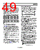
49 / 140 page  Data Sheet ADP1055 Rev. A | Page 49 of 140 GROUP COMMAND PROTOCOL In addition to the communication protocols described in the Data Transfer Commands section, the PMBus slave supports a special group command in which commands are sent to multiple slaves in a single serial transmission. The commands to each slave can be different from one another, with each set of {slave- address, command} separated by a repeated start (Sr) bit (see Figure 78). At the end of a transmission to all slaves, a single stop (P) bit is sent to initiate concurrent execution of the received commands by all slaves. Note that the PEC byte transmitted to each slave is calculated using only its slave address, command code, and data bytes. Figure 78. Group Command Protocol with PEC CLOCK GENERATION AND STRETCHING The ADP1055 is always a PMBus slave device in the overall system; therefore, the device never needs to generate the clock, which is done by the master device in the system. However, the PMBus slave device is capable of clock stretching to put the master in a wait state. By stretching the SCL signal during the low period, the slave device communicates to the master device that it is not ready and that the master device must wait. Conditions where the PMBus slave device stretches the SCL line low include the following: Master device is transmitting at a higher baud rate than the slave device. Receive FIFO buffer of the slave device is full and must be read before continuing to prevent a data overflow condition. Slave device is not ready to send data that the master has requested. Note that the slave device can stretch the SCL line only during the low period. Also, whereas the I2C specification allows indefinite stretching of the SCL line, the PMBus specification limits the maximum time that the SCL line can be stretched, or held low, to 25 ms, after which the ADP1055 must release the communica- tion lines and reset its state machine. START AND STOP CONDITIONS Start and stop conditions involve serial data transitions while the serial clock is at a logic high level. The PMBus slave device monitors the SDA and SCL lines to detect the start and stop conditions and transition its internal state machine accordingly. Figure 79 shows typical start and stop conditions. Figure 79. Start and Stop Transitions REPEATED START CONDITION In general, a repeated start (Sr) condition is the absence of a stop condition between two transfers. The PMBus communication protocol makes use of the repeated start condition only when performing a read access (read byte, read word, and block read). Other uses of the repeated start condition are not allowed. GENERAL CALL SUPPORT The PMBus slave is capable of decoding and acknowledging a general call address. The PMBus device responds to both its own address and the general call address (0x00). Note that all PMBus commands must start with the slave address with the R/W bit cleared (set to 0), followed by the command code. This is also true when using the general call address to communi- cate with the PMBus slave device. The only exception to this rule is when the SMBALRT alert response address is used. ALERT RESPONSE ADDRESS (ARA) If a PMBus slave device supports the SMBALRT hardware pin to interrupt the master on a fault condition, the SMBus Alert Response Address Protocol must be supported to allow commu- nication between the master and slave on the device that triggers the fault. When the SMBALRT pin on the slave is asserted, the master queries the address of the slave device that triggered the fault by sending the alert response address (0001 to 100x). In response to this address, the slave with the asserted SMBALRT pin acknowledges (ACKs) the address and responds with its own slave address (7-bit address and plus 0). If multiple slave devices have their SMBALRT pins asserted, the slave with the lowest address wins the arbitration and subsequently deasserts its SMBALRT pin. Figure 80. ARA Protocol with PEC S SLAVE 1 ADDRESS SLAVE 2 ADDRESS DATA 1 . . . N W A A A COMMAND CODE 1 PEC 1 Sr DATA 1 . . . N W A A A A A A COMMAND CODE 2 PEC 2 SLAVE M ADDRESS Sr DATA 1 . . . N W A A P A COMMAND CODE M PEC M = MASTER-TO-SLAVE = SLAVE-TO-MASTER S 7-BIT ARA x A A A P SLAVE ADDRESS PEC BYTE = MASTER-TO-SLAVE = SLAVE-TO-MASTER |
|
ссылки URL |
| Вашему бизинису помогли Аллдатащит? [ DONATE ] |
Что такое Аллдатащит | реклама | контакт | Конфиденциальность | Ссылка на техническое описание | обмен ссыками | поиск по производителю All Rights Reserved©Alldatasheet.com |
| Russian : Alldatasheetru.com | Korean : Alldatasheet.co.kr | Spanish : Alldatasheet.es | French : Alldatasheet.fr | Italian : Alldatasheetit.com Portuguese : Alldatasheetpt.com | Polish : Alldatasheet.pl | Vietnamese : Alldatasheet.vn Indian : Alldatasheet.in | Mexican : Alldatasheet.com.mx | British : Alldatasheet.co.uk | New Zealand : Alldatasheet.co.nz |
|
Family Site : ic2ic.com |
icmetro.com |
 Russian ▼
 English
 Chinese
 German
 Japanese
 Russian
 Korean
 Spanish
 French
 Italian
 Portuguese
 Polish
 Vietnamese
 Indian
 Mexican
 British
 New Zealand