|
поискавой системы для электроныых деталей |
|
|
поискавой системы для электроныых деталей |
|
ADP1055ACPZ-R7 датащи(PDF) 38 Page - Analog Devices |
|
|
|||||||||||||||||||||||||||||
ADP1055ACPZ-R7 датащи(HTML) 38 Page - Analog Devices |
|
|
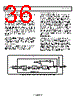
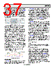
38 / 140 page  ADP1055 Data Sheet Rev. A | Page 38 of 140 DUTY BALANCE, VOLT-SECOND BALANCE, AND FLUX BALANCING For power topologies that use the first and third quadrant of the BH curve, it is recommended that duty balance be enabled when using double update rate. Due to the nature of double update rate, it is possible that the average magnetizing current (and therefore the flux density of the transformer core) is not zero, but is equal to some positive or negative dc level. To prevent flux walking and an imbalance in the transformer, a combination of the duty balance and volt-second balance features can be used. In interleaved topologies, the volt-second balance feature can also be used for current balancing to ensure that each interleaved phase contributes equal power. For example, if a full bridge topology requires the diagonal edges of the H bridge to be equalized, the algorithm for duty balance averages the duty cycle over several switching cycles. Duty balance is a purely digital correction that is applied to the PWM edges based on past duty cycles and does not take into account any feedback from an ADC, as is the case for volt-second balance. Duty balance is enabled by setting Register 0xFE57[7] = 1; the speed at which the duty cycle is balanced is controlled by setting Register 0xFE57[5:4]. Additionally, the extent to which duty cycle correction (maximum of ±160 ns for duty balance and volt-second balance each) can take place is specified using Register 0xFE57[2:1]. Volt-second balance uses a sample-and-hold circuit (patent pending) that samples the peak current during both halves of the switching period. This feature is configured using Register 0xFE56. The recommended settings for using the volt-second balance feature are as follows. 1. Use Register 0xFE56 to set the positive and negative edges. Bits[7:4] set the positive period of integration, and Bits[3:0] set the negative period of integration. The edges are logically AND’ed together. Typically, the diagonal edges of the H bridge are balanced. For example, in a full bridge topology, a setting of 10010110 for Register 0xFE56 causes the device to sample the peak current at the end of the logical AND of OUTA and OUTD (Peak 1) and the logical AND of OUTB and OUTC (Peak 2). If Peak 1 > Peak 2, the result is positive and the duty cycle of the selected edges is reduced. If Peak 2 > Peak 1, the result is negative and the duty cycle of the selected edges is increased. 2. Apply edge correction. Using the same example, negative edge correction is applied to OUTA and OUTD, whereas positive edge correction is applied to OUTB and OUTC. Appropriate edge correction is applied to the SR outputs as well. 3. Enable volt-second balance by setting Register 0xFE25[6] = 1. This setting is gated by a GO command (Register 0xFE00). Volt-second balance is automatically disabled when the voltage on the CS1 pin is below 25 mV. Figure 64. Volt-Second Balance with Register 0xFE56 = 0x96 Figure 65. Volt-Second Balance with Register 0xFE56 = 0x69 Figure 66. Simplified Internal Structure of the Volt-Second Balance Circuit VS BALANCE ALGORITHM SAMPLE AND HOLD WITH RESET VS BALANCE EDGE SELECT REGISTERS PWM VIN VOUT SR1 SR2 OUTA OUTB OUTC OUTD CS1 INPUT ADP1055 |
|
ссылки URL |
| Вашему бизинису помогли Аллдатащит? [ DONATE ] |
Что такое Аллдатащит | реклама | контакт | Конфиденциальность | Ссылка на техническое описание | обмен ссыками | поиск по производителю All Rights Reserved©Alldatasheet.com |
| Russian : Alldatasheetru.com | Korean : Alldatasheet.co.kr | Spanish : Alldatasheet.es | French : Alldatasheet.fr | Italian : Alldatasheetit.com Portuguese : Alldatasheetpt.com | Polish : Alldatasheet.pl | Vietnamese : Alldatasheet.vn Indian : Alldatasheet.in | Mexican : Alldatasheet.com.mx | British : Alldatasheet.co.uk | New Zealand : Alldatasheet.co.nz |
|
Family Site : ic2ic.com |
icmetro.com |
 Russian ▼
 English
 Chinese
 German
 Japanese
 Russian
 Korean
 Spanish
 French
 Italian
 Portuguese
 Polish
 Vietnamese
 Indian
 Mexican
 British
 New Zealand