|
поискавой системы для электроныых деталей |
|
|
поискавой системы для электроныых деталей |
|
ADP1055ACPZ-R7 датащи(PDF) 89 Page - Analog Devices |
|
|
|||||||||||||||||||||||||||||
ADP1055ACPZ-R7 датащи(HTML) 89 Page - Analog Devices |
|
|
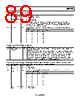
89 / 140 page  Data Sheet ADP1055 Rev. A | Page 89 of 140 Table 146. Register 0xFE1D—ADT_CONFIG Bits Bit Name R/W Description 7 Averaging period R/W 1 = 9-bit averaging (327 μs). 0 = 12-bit averaging (2.6 ms). 6 ADT reference R/W 0 = CS1 as reference. 1 = CS2 as reference. [5:3] Update rate R/W The ADT algorithm adjusts the dead time in steps of 5 ns. These bits are used to program the number of PWM switching cycles between each step. The number is calculated as 2N + 1, where N is the 3-bit value specified by these bits. If N = 6 (110), each PWM edge is adjusted by 5 ns every 26 + 1 = 65 switching cycles. [2:0] Multiplier R/W These bits specify the programming step for Register 0xFE1F to Register 0xFE22, Bits[6:4] and Bits[2:0]. Bit 2 Bit 1 Bit 0 Multiplier 0 0 0 5 0 0 1 10 0 1 0 15 0 1 1 20 1 0 0 25 1 0 1 30 1 1 0 35 1 1 1 40 Table 147. Register 0xFE1E—ADT_THRESHOLD Bits Bit Name R/W Description [7:0] Adaptive dead time threshold R/W This register sets the ADT threshold. This 8-bit number is compared to the eight MSBs of the CS1/CS2 value register. When the current level measured on CS1/CS2 falls below this threshold, the edges of the PWM signals are affected as a linear function of the CS1/CS2 current, as programmed in Register 0xFE1F to Register 0xFE24. When this register is programmed to 0x00, the ADT function is disabled. When CS1 is used as the reference, each LSB in this register corresponds to 1.6 V/28 = 6.25 mV. When CS2 is used as the reference, each LSB in this register corresponds to 26.25 mV, 52.5 mV, or 420 mV]/28 = 102.539 μV, 205.078 μV, or 1640.625 μV. Also note that when CS2 is used as the reference, the maximum allowed value in this register is 224 (0xE0). Table 148. Register 0xFE1F, Register 0xFE20, Register 0xFE21, Register 0xFE22—OUTA_DEAD_TIME, OUTB_DEAD_TIME, OUTC_DEAD_TIME, OUTD_DEAD_TIME (Requires Use of the GO Bit in Register 0xFE00) Bits Bit Name R/W Description 7 t1, t3, t5, t7, t9, t11 polarity R/W 0 = positive polarity. 1 = negative polarity. [6:4] t1, t3, t5, t7, t9, t11 offset R/W This value multiplied by Register 0xFE1D[2:0] determines the offset for t1, t3, t5, t7, t9, t11 from nominal timing at no load. Bit 6 Bit 5 Bit 4 Offset (ns) 0 0 0 0 0 0 1 1 0 1 0 2 0 1 1 3 1 0 0 4 1 0 1 5 1 1 0 6 1 1 1 7 3 t2, t4, t6, t8, t10, t12 polarity R/W 0 = positive polarity. 1 = negative polarity. |
|
ссылки URL |
| Вашему бизинису помогли Аллдатащит? [ DONATE ] |
Что такое Аллдатащит | реклама | контакт | Конфиденциальность | Ссылка на техническое описание | обмен ссыками | поиск по производителю All Rights Reserved©Alldatasheet.com |
| Russian : Alldatasheetru.com | Korean : Alldatasheet.co.kr | Spanish : Alldatasheet.es | French : Alldatasheet.fr | Italian : Alldatasheetit.com Portuguese : Alldatasheetpt.com | Polish : Alldatasheet.pl | Vietnamese : Alldatasheet.vn Indian : Alldatasheet.in | Mexican : Alldatasheet.com.mx | British : Alldatasheet.co.uk | New Zealand : Alldatasheet.co.nz |
|
Family Site : ic2ic.com |
icmetro.com |
 Russian ▼
 English
 Chinese
 German
 Japanese
 Russian
 Korean
 Spanish
 French
 Italian
 Portuguese
 Polish
 Vietnamese
 Indian
 Mexican
 British
 New Zealand