|
поискавой системы для электроныых деталей |
|
|
поискавой системы для электроныых деталей |
|
ADP1055ACPZ-R7 датащи(PDF) 120 Page - Analog Devices |
|
|
|||||||||||||||||||||||||||||
ADP1055ACPZ-R7 датащи(HTML) 120 Page - Analog Devices |
|
|
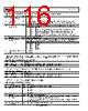
120 / 140 page  ADP1055 Data Sheet Rev. A | Page 120 of 140 Table 210. Register 0xFE62—LOW_TEMP_SETTING Bits Bit Name R/W Description 7 ADD_PZ configuration R/W 0 = ADD_PZ is configured as a digital pole. 1 = ADD_PZ is configured as a digital zero. [6:4] Low temperature threshold R/W If non-zero, the filter switches from the NMF (normal mode filter) to the SS filter (soft start filter) in steps of ±4°C. 000 = regular filter operation independent of temperature unless the sensing point (configured in Bits[1:0]) is set to GPIO2 (the filter then changes based on the GPIO2 pin). 001 = below −14°C, the soft start filter is used for regulation instead of the normal mode filter. 010 = below −10°C, the soft start filter is used for regulation instead of the normal mode filter. 011 = below −6°C, the soft start filter is used for regulation instead of the normal mode filter. 100 = below −2°C, the soft start filter is used for regulation instead of the normal mode filter. 101 = below +2°C, the soft start filter is used for regulation instead of the normal mode filter. 110 = below +6°C, the soft start filter is used for regulation instead of the normal mode filter. 111 = below +10°C, the soft start filter is used for regulation instead of the normal mode filter. [3:2] Low temperature hysteresis R/W Each bit is 5°C of hysteresis. 00 = 5°C. 01 = 10°C. 10 = 15°C. 11 = 20°C. [1:0] Low temperature sensing point R/W 00 = reserved. 01 = external FWD temperature sensing. 10 = external REV temperature sensing. 11 = rising edge of GPIO2. Table 211. Register 0xFE63—GPIO3_4_SNUBBER_ON_TIME Bits Bit Name R/W Description [7:0] Snubber on time R/W Maximum on time of GPIO3/GPIO4 (if SR/OUTC/OUTD goes high, then the GPIO3/GPIO4 output goes low/high) in units of 20 ns 0x00 = 0 ns 0x01 = 20 ns … 0xFE = 5.08 μs 0xFF = on until SRx goes high or OUTC or OUTD goes low Table 212. Register 0xFE64—GPIO3_4_SNUBBER_DELAY Bits Bit Name R/W Description [7:6] GPIO4 snubber enable R/W 00 = disable active snubber on GPIO3/GPIO4. 01 = only GPIO3 is active snubber. GPIO3 goes high after the snubber delay time in Register 0xFE64[5:0]. 10 = only GPIO4 is active snubber. GPIO4 goes high after the snubber delay time in Register 0xFE64[5:0]. 11 = GPIO3 and GPIO4 are active snubber outputs. GPIO3 is the inverse of SR1 or OUTC; GPIO4 is the inverse of SR2 or OUTC, depending on Register 0xFE65[7]. [5:0] Snubber delay R/W Dead time delay from fall of SR to rise of GPIO3/GPIO4, in units of 5 ns, regardless of the polarity of GPIO3/GPIO4. 0x00 = 0 ns. 0x01 = 5 ns. 0x3F = 315 ns. |
|
ссылки URL |
| Вашему бизинису помогли Аллдатащит? [ DONATE ] |
Что такое Аллдатащит | реклама | контакт | Конфиденциальность | Ссылка на техническое описание | обмен ссыками | поиск по производителю All Rights Reserved©Alldatasheet.com |
| Russian : Alldatasheetru.com | Korean : Alldatasheet.co.kr | Spanish : Alldatasheet.es | French : Alldatasheet.fr | Italian : Alldatasheetit.com Portuguese : Alldatasheetpt.com | Polish : Alldatasheet.pl | Vietnamese : Alldatasheet.vn Indian : Alldatasheet.in | Mexican : Alldatasheet.com.mx | British : Alldatasheet.co.uk | New Zealand : Alldatasheet.co.nz |
|
Family Site : ic2ic.com |
icmetro.com |
 Russian ▼
 English
 Chinese
 German
 Japanese
 Russian
 Korean
 Spanish
 French
 Italian
 Portuguese
 Polish
 Vietnamese
 Indian
 Mexican
 British
 New Zealand