|
поискавой системы для электроныых деталей |
|
|
поискавой системы для электроныых деталей |
|
TMS320LC2401AVFS датащи(PDF) 16 Page - Texas Instruments |
|
|
|||||||||||||||||||||||||||||
TMS320LC2401AVFS датащи(HTML) 16 Page - Texas Instruments |
|
|
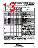
16 / 134 page  TMS320LF2407A,TMS320LF2406A,TMS320LF2403A,TMS320LF2402A TMS320LC2406A,TMS320LC2404A,TMS320LC2403A,TMS320LC2402A DSP CONTROLLERS SPRS145K − JULY 2000 − REVISED AUGUST 2005 16 POST OFFICE BOX 1443 • HOUSTON, TEXAS 77251−1443 pin functions (continued) Table 2. LF240xA and LC240xA Pin List and Package Options†‡ (Continued) PIN NAME LF2407A (144-PGE) 2406A (100-PZ) LC2404A (100-PZ) 2403A, LC2402A (64-PAG) and 2402A (64-PG) DESCRIPTION EMULATION AND TEST (CONTINUED) TDI 139 96 96 30 JTAG test data input (TDI) with internal pullup. TDI is clocked into the selected register (instruction or data) on a rising edge of TCK. ( ↑) TDO 142 99 99 31 JTAG scan out, test data output (TDO). The contents of the selected register (instruction or data) is shifted out of TDO on the falling edge of TCK. ( ↓) TMS 144 100 100 32 JTAG test-mode select (TMS) with internal pullup. This serial control input is clocked into the TAP controller on the rising edge of TCK. ( ↑) TMS2 36 25 25 48 JTAG test-mode select 2 (TMS2) with internal pullup. This serial control input is clocked into the TAP controller on the rising edge of TCK. Used for test and emulation only. This pin can be left unconnected in user applications. If the PLL bypass mode is desired, TMS2, TMS, and TRST should be held low during reset. ( ↑) TRST 1 1 1 33 JTAG test reset with internal pulldown. TRST, when driven high, gives the scan system control of the operations of the device. If this signal is not connected or driven low, the device operates in its functional mode, and the test reset signals are ignored. ( ↓) NOTE: Do not use pullup resistors on TRST; it has an internal pulldown device. TRST is an active high test pin and must be maintained low at all times during normal device operation. In a low-noise environment, TRST may be left floating. In other instances, an external pulldown resistor is highly recommended. The value of this resistor should be based on drive strength of the debugger pods applicable to the design. A 2.2-k Ω resistor generally offers adequate protection. Since this is application−specific, it is recommended that each target board be validated for proper operation of the debugger and the application. (I ↓) † Bold, italicized pin names indicate pin function after reset. ‡ GPIO − General-purpose input/output pin. All GPIOs come up as input after reset. § It is highly recommended that VCCA be isolated from the digital supply voltage (and VSSA from digital ground) to maintain the specified accuracy and improve the noise immunity of the ADC. ¶ Only when all of the following conditions are met: EMU1/OFF is low, TRST is low, and EMU0 is high # No power supply pin (VDD, VDDO, VSS, or VSSO) should be left unconnected. All power supply pins must be connected appropriately for proper device operation. LEGEND: ↑ − Internal pullup ↓ − Internal pulldown (Typical active pullup/pulldown value is ±16 µA.) |
|
ссылки URL |
| Вашему бизинису помогли Аллдатащит? [ DONATE ] |
Что такое Аллдатащит | реклама | контакт | Конфиденциальность | Ссылка на техническое описание | обмен ссыками | поиск по производителю All Rights Reserved©Alldatasheet.com |
| Russian : Alldatasheetru.com | Korean : Alldatasheet.co.kr | Spanish : Alldatasheet.es | French : Alldatasheet.fr | Italian : Alldatasheetit.com Portuguese : Alldatasheetpt.com | Polish : Alldatasheet.pl | Vietnamese : Alldatasheet.vn Indian : Alldatasheet.in | Mexican : Alldatasheet.com.mx | British : Alldatasheet.co.uk | New Zealand : Alldatasheet.co.nz |
|
Family Site : ic2ic.com |
icmetro.com |
 Russian ▼
 English
 Chinese
 German
 Japanese
 Russian
 Korean
 Spanish
 French
 Italian
 Portuguese
 Polish
 Vietnamese
 Indian
 Mexican
 British
 New Zealand