|
поискавой системы для электроныых деталей |
|
|
поискавой системы для электроныых деталей |
|
TMS320LC2401AVFS датащи(PDF) 15 Page - Texas Instruments |
|
|
|||||||||||||||||||||||||||||
TMS320LC2401AVFS датащи(HTML) 15 Page - Texas Instruments |
|
|
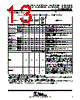
15 / 134 page  TMS320LF2407A,TMS320LF2406A,TMS320LF2403A,TMS320LF2402A TMS320LC2406A,TMS320LC2404A,TMS320LC2403A,TMS320LC2402A DSP CONTROLLERS SPRS145K − JULY 2000 − REVISED AUGUST 2005 15 POST OFFICE BOX 1443 • HOUSTON, TEXAS 77251−1443 pin functions (continued) Table 2. LF240xA and LC240xA Pin List and Package Options†‡ (Continued) PIN NAME LF2407A (144-PGE) 2406A (100-PZ) LC2404A (100-PZ) 2403A, LC2402A (64-PAG) and 2402A (64-PG) DESCRIPTION OSCILLATOR, PLL, FLASH, BOOT, AND MISCELLANEOUS (CONTINUED) PLLF2 10 8 8 37 PLL loop filter input 2 VCCP (5V) 58 40 40 60 Flash programming voltage pin. This pin must be connected to a 5-V supply for Flash programming. The Flash cannot be programmed if this pin is connected to GND. When not programming the Flash (i.e., during normal device operation), this pin can either be left connected to the 5-V supply or it can be tied to GND. This pin must not be left floating at any time. Do not use any current-limiting resistor in series with the 5-V supply on this pin. This pin is a “no connect” (NC) on ROM parts (i.e., this pin is not connected to any circuitry internal to the device). Connecting this pin to 5 V or leaving it open makes no difference on ROM parts. TP1 60 42 42 61 Test pin 1. Do not connect. TP2 63 44 44 62 Test pin 2. Do not connect. BIO/IOPC1 119 85 85 Branch control input. BIO is polled by the BCND pma,BIO instruction. If BIO is low, a branch is executed. If BIO is not used, it should be pulled high. This pin is configured as a branch control input by all device resets. It can be used as a GPIO, if not used as a branch control input. ( ↑) EMULATION AND TEST EMU0 90 61 61 7 Emulator I/O #0 with internal pullup. When TRST is driven high, this pin is used as an interrupt to or from the emulator system and is defined as input/output through the JTAG scan. ( ↑) EMU1/OFF 91 62 62 8 Emulator pin 1. Emulator pin 1 disables all outputs. When TRST is driven high, EMU1/OFF is used as an interrupt to or from the emulator system and is defined as an input/output through the JTAG scan. When TRST is driven low, this pin is configured as OFF. EMU1/OFF, when active low, puts all output drivers in the high-impedance state. Note that OFF is used exclusively for testing and emulation purposes (not for multiprocessing applications). Therefore, for the OFF condition, the following apply: TRST = 0 EMU0 = 1 EMU1/OFF = 0 ( ↑) TCK 135 94 94 29 JTAG test clock with internal pullup ( ↑) † Bold, italicized pin names indicate pin function after reset. ‡ GPIO − General-purpose input/output pin. All GPIOs come up as input after reset. § It is highly recommended that VCCA be isolated from the digital supply voltage (and VSSA from digital ground) to maintain the specified accuracy and improve the noise immunity of the ADC. ¶ Only when all of the following conditions are met: EMU1/OFF is low, TRST is low, and EMU0 is high # No power supply pin (VDD, VDDO, VSS, or VSSO) should be left unconnected. All power supply pins must be connected appropriately for proper device operation. LEGEND: ↑ − Internal pullup ↓ − Internal pulldown (Typical active pullup/pulldown value is ±16 µA.) |
|
ссылки URL |
| Вашему бизинису помогли Аллдатащит? [ DONATE ] |
Что такое Аллдатащит | реклама | контакт | Конфиденциальность | Ссылка на техническое описание | обмен ссыками | поиск по производителю All Rights Reserved©Alldatasheet.com |
| Russian : Alldatasheetru.com | Korean : Alldatasheet.co.kr | Spanish : Alldatasheet.es | French : Alldatasheet.fr | Italian : Alldatasheetit.com Portuguese : Alldatasheetpt.com | Polish : Alldatasheet.pl | Vietnamese : Alldatasheet.vn Indian : Alldatasheet.in | Mexican : Alldatasheet.com.mx | British : Alldatasheet.co.uk | New Zealand : Alldatasheet.co.nz |
|
Family Site : ic2ic.com |
icmetro.com |
 Russian ▼
 English
 Chinese
 German
 Japanese
 Russian
 Korean
 Spanish
 French
 Italian
 Portuguese
 Polish
 Vietnamese
 Indian
 Mexican
 British
 New Zealand