|
поискавой системы для электроныых деталей |
|
|
поискавой системы для электроныых деталей |
|
PIC16C71 датащи(PDF) 89 Page - Microchip Technology |
|
|
|||||||||||||||||||||||||||||
PIC16C71 датащи(HTML) 89 Page - Microchip Technology |
|
|
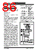
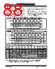
89 / 337 page  © 1997 Microchip Technology Inc. DS30234D-page 89 PIC16C6X 11.3 SPI Mode for PIC16C66/67 This section contains register definitions and opera- tional characterisitics of the SPI module on the PIC16C66 and PIC16C67 only. FIGURE 11-7: SSPSTAT: SYNC SERIAL PORT STATUS REGISTER (ADDRESS 94h)(PIC16C66/67) R/W-0 R/W-0 R-0 R-0 R-0 R-0 R-0 R-0 SMP CKE D/A P S R/W UA BF R = Readable bit W = Writable bit U = Unimplemented bit, read as ‘0’ - n =Value at POR reset bit7 bit0 bit 7: SMP: SPI data input sample phase SPI Master Mode 1 = Input data sampled at end of data output time 0 = Input data sampled at middle of data output time SPI Slave Mode SMP must be cleared when SPI is used in slave mode bit 6: CKE: SPI Clock Edge Select (Figure 11-11, Figure 11-12, and Figure 11-13) CKP = 0 1 = Data transmitted on rising edge of SCK 0 = Data transmitted on falling edge of SCK CKP = 1 1 = Data transmitted on falling edge of SCK 0 = Data transmitted on rising edge of SCK bit 5: D/A: Data/Address bit (I2C mode only) 1 = Indicates that the last byte received or transmitted was data 0 = Indicates that the last byte received or transmitted was address bit 4: P: Stop bit (I2C mode only. This bit is cleared when the SSP module is disabled, or when the Start bit is detected last, SSPEN is cleared) 1 = Indicates that a stop bit has been detected last (this bit is '0' on RESET) 0 = Stop bit was not detected last bit 3: S: Start bit (I2C mode only. This bit is cleared when the SSP module is disabled, or when the Stop bit is detected last, SSPEN is cleared) 1 = Indicates that a start bit has been detected last (this bit is '0' on RESET) 0 = Start bit was not detected last bit 2: R/W: Read/Write bit information (I2C mode only) This bit holds the R/W bit information following the last address match. This bit is only valid from the address match to the next start bit, stop bit, or ACK bit. 1 = Read 0 = Write bit 1: UA: Update Address (10-bit I2C mode only) 1 = Indicates that the user needs to update the address in the SSPADD register 0 = Address does not need to be updated bit 0: BF: Buffer Full Status bit Receive (SPI and I2C modes) 1 = Receive complete, SSPBUF is full 0 = Receive not complete, SSPBUF is empty Transmit (I2C mode only) 1 = Transmit in progress, SSPBUF is full 0 = Transmit complete, SSPBUF is empty Applicable Devices 61 62 62A R62 63 R63 64 64A R64 65 65A R65 66 67 |
|
ссылки URL |
| Вашему бизинису помогли Аллдатащит? [ DONATE ] |
Что такое Аллдатащит | реклама | контакт | Конфиденциальность | Ссылка на техническое описание | обмен ссыками | поиск по производителю All Rights Reserved©Alldatasheet.com |
| Russian : Alldatasheetru.com | Korean : Alldatasheet.co.kr | Spanish : Alldatasheet.es | French : Alldatasheet.fr | Italian : Alldatasheetit.com Portuguese : Alldatasheetpt.com | Polish : Alldatasheet.pl | Vietnamese : Alldatasheet.vn Indian : Alldatasheet.in | Mexican : Alldatasheet.com.mx | British : Alldatasheet.co.uk | New Zealand : Alldatasheet.co.nz |
|
Family Site : ic2ic.com |
icmetro.com |
 Russian ▼
 English
 Chinese
 German
 Japanese
 Russian
 Korean
 Spanish
 French
 Italian
 Portuguese
 Polish
 Vietnamese
 Indian
 Mexican
 British
 New Zealand