|
поискавой системы для электроныых деталей |
|
|
поискавой системы для электроныых деталей |
|
PIC16C71 датащи(PDF) 81 Page - Microchip Technology |
|
|
|||||||||||||||||||||||||||||
PIC16C71 датащи(HTML) 81 Page - Microchip Technology |
|
|
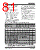
81 / 337 page  © 1997 Microchip Technology Inc. DS30234D-page 81 PIC16C6X EXAMPLE 10-2: PWM PERIOD AND DUTY CYCLE CALCULATION Desired PWM frequency is 78.125 kHz, Fosc = 20 MHz TMR2 prescale = 1 1/78.125 kHz = [(PR2) + 1] • 4 • 1/20 MHz • 1 12.8 µs = [(PR2) + 1] • 4 • 50 ns • 1 PR2 = 63 Find the maximum resolution of the duty cycle that can be used with a 78.125 kHz frequency and 20 MHz oscillator: 1/78.125 kHz = 2 PWM RESOLUTION • 1/20 MHz • 1 12.8 µs= 2PWM RESOLUTION • 50 ns • 1 256 = 2 PWM RESOLUTION log(256) = (PWM Resolution) • log(2) 8.0 = PWM Resolution At most, an 8-bit resolution duty cycle can be obtained from a 78.125 kHz frequency and a 20 MHz oscillator, i.e., 0 ≤ CCPR1L:CCP1CON<5:4> ≤ 255. Any value greater than 255 will result in a 100% duty cycle. In order to achieve higher resolution, the PWM fre- quency must be decreased. In order to achieve higher PWM frequency, the resolution must be decreased. Table 10-3 lists example PWM frequencies and resolu- tions for Fosc = 20 MHz. The TMR2 prescaler and PR2 values are also shown. 10.3.3 SET-UP FOR PWM OPERATION The following steps should be taken when configuring the CCP module for PWM operation: 1. Set the PWM period by writing to the PR2 regis- ter. 2. Set the PWM duty cycle by writing to the CCPR1L register and CCP1CON<5:4> bits. 3. Make the CCP1 pin an output by clearing the TRISC<2> bit. 4. Set the TMR2 prescale value and enable Timer2 by writing to T2CON. 5. Configure the CCP1 module for PWM operation. TABLE 10-3: EXAMPLE PWM FREQUENCIES AND RESOLUTIONS AT 20 MHz TABLE 10-4: REGISTERS ASSOCIATED WITH TIMER1, CAPTURE AND COMPARE PWM Frequency 1.22 kHz 4.88 kHz 19.53 kHz 78.12 kHz 156.3 kHz 208.3 kHz Timer Prescaler (1, 4, 16) 16 4 1111 PR2 Value 0xFF 0xFF 0xFF 0x3F 0x1F 0x17 Maximum Resolution (bits) 10 10 10 8 7 5.5 Add Name Bit 7 Bit 6 Bit 5 Bit 4 Bit 3 Bit 2 Bit 1 Bit 0 Value on: POR, BOR Value on all other Resets 0Bh,8Bh 10Bh,18Bh INTCON GIE PEIE T0IE INTE RBIE T0IF INTF RBIF 0000 000x 0000 000u 0Ch PIR1 PSPIF(2) (3) RCIF(1) TXIF(1) SSPIF CCP1IF TMR2IF TMR1IF 0000 0000 0000 0000 0Dh(4) PIR2 — — — — — — — CCP2IF ---- ---0 ---- ---0 8Ch PIE1 PSPIE(2) (3) RCIE(1) TXIE(1) SSPIE CCP1IE TMR2IE TMR1IE 0000 0000 0000 0000 8Dh(4) PIE2 — — — — — — — CCP2IE ---- ---0 ---- ---0 87h TRISC PORTC Data Direction register 1111 1111 1111 1111 0Eh TMR1L Holding register for the Least Significant Byte of the 16-bit TMR1 register xxxx xxxx uuuu uuuu 0Fh TMR1H Holding register for the Most Significant Byte of the 16-bit TMR1 register xxxx xxxx uuuu uuuu 10h T1CON — — T1CKPS1 T1CKPS0 T1OSCEN T1SYNC TMR1CS TMR1ON --00 0000 --uu uuuu 15h CCPR1L Capture/Compare/PWM1 (LSB) xxxx xxxx uuuu uuuu 16h CCPR1H Capture/Compare/PWM1 (MSB) xxxx xxxx uuuu uuuu 17h CCP1CON — — CCP1X CCP1Y CCP1M3 CCP1M2 CCP1M1 CCP1M0 --00 0000 --00 0000 1Bh(4) CCPR2L Capture/Compare/PWM2 (LSB) xxxx xxxx uuuu uuuu 1Ch(4) CCPR2H Capture/Compare/PWM2 (MSB) xxxx xxxx uuuu uuuu 1Dh(4) CCP2CON — — CCP2X CCP2Y CCP2M3 CCP2M2 CCP2M1 CCP2M0 --00 0000 --00 0000 Legend: x = unknown, u = unchanged, - = unimplemented locations read as '0’. Shaded cells are not used in these modes. Note 1: These bits are associated with the USART module, which is implemented on the PIC16C63/R63/65/65A/R65/66/67 only. 2: Bits PSPIE and PSPIF are reserved on the PIC16C62/62A/R62/63/R63/66, always maintain these bits clear. 3: The PIR1<6> and PIE1<6> bits are reserved, always maintain these bits clear. 4: These registers are associated with the CCP2 module, which is only implemented on the PIC16C63/R63/65/65A/R65/66/67. |
|
ссылки URL |
| Вашему бизинису помогли Аллдатащит? [ DONATE ] |
Что такое Аллдатащит | реклама | контакт | Конфиденциальность | Ссылка на техническое описание | обмен ссыками | поиск по производителю All Rights Reserved©Alldatasheet.com |
| Russian : Alldatasheetru.com | Korean : Alldatasheet.co.kr | Spanish : Alldatasheet.es | French : Alldatasheet.fr | Italian : Alldatasheetit.com Portuguese : Alldatasheetpt.com | Polish : Alldatasheet.pl | Vietnamese : Alldatasheet.vn Indian : Alldatasheet.in | Mexican : Alldatasheet.com.mx | British : Alldatasheet.co.uk | New Zealand : Alldatasheet.co.nz |
|
Family Site : ic2ic.com |
icmetro.com |
 Russian ▼
 English
 Chinese
 German
 Japanese
 Russian
 Korean
 Spanish
 French
 Italian
 Portuguese
 Polish
 Vietnamese
 Indian
 Mexican
 British
 New Zealand