|
поискавой системы для электроныых деталей |
|
|
поискавой системы для электроныых деталей |
|
PIC16C71 датащи(PDF) 88 Page - Microchip Technology |
|
|
|||||||||||||||||||||||||||||
PIC16C71 датащи(HTML) 88 Page - Microchip Technology |
|
|
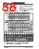
88 / 337 page  PIC16C6X DS30234D-page 88 © 1997 Microchip Technology Inc. The SS pin allows a synchronous slave mode. The SPI must be in slave mode (SSPCON<3:0> = 04h) and the TRISA<5> bit must be set the for synchro- nous slave mode to be enabled. When the SS pin is low, transmission and reception are enabled and the SDO pin is driven. When the SS pin goes high, the SDO pin is no longer driven, even if in the mid- dle of a transmitted byte, and becomes a floating output. If the SS pin is taken low without resetting SPI mode, the transmission will continue from the point at which it was taken high. External pull-up/ pull-down resistors may be desirable, depending on the application. To emulate two-wire communication, the SDO pin can be connected to the SDI pin. When the SPI needs to operate as a receiver the SDO pin can be configured as an input. This disables transmissions from the SDO. The SDI can always be left as an input (SDI function) since it cannot create a bus conflict. FIGURE 11-5: SPI MODE TIMING, MASTER MODE OR SLAVE MODE W/O SS CONTROL FIGURE 11-6: SPI MODE TIMING, SLAVE MODE WITH SS CONTROL TABLE 11-1: REGISTERS ASSOCIATED WITH SPI OPERATION Address Name Bit 7 Bit 6 Bit 5 Bit 4 Bit 3 Bit 2 Bit 1 Bit 0 Value on: POR, BOR Value on all other Resets 0Bh,8Bh INTCON GIE PEIE T0IE INTE RBIE T0IF INTF RBIF 0000 000x 0000 000u 0Ch PIR1 PSPIF(2) (3) RCIF(1) TXIF(1) SSPIF CCP1IF TMR2IF TMR1IF 0000 0000 0000 0000 8Ch PIE1 PSPIE(2) (3) RCIE(1) TXIE(1) SSPIE CCP1IE TMR2IE TMR1IE 0000 0000 0000 0000 13h SSPBUF Synchronous Serial Port Receive Buffer/Transmit Register xxxx xxxx uuuu uuuu 14h SSPCON WCOL SSPOV SSPEN CKP SSPM3 SSPM2 SSPM1 SSPM0 0000 0000 0000 0000 85h TRISA — — PORTA Data Direction Register --11 1111 --11 1111 87h TRISC PORTC Data Direction Register 1111 1111 1111 1111 94h SSPSTAT — — D/A P S R/W UA BF --00 0000 --00 0000 Legend: x = unknown, u = unchanged, - = unimplemented locations read as '0'. Shaded cells are not used by SSP module in SPI mode. Note 1: These bits are associated with the USART which is implemented on the PIC16C63/R63/65/65A/R65 only. 2: PSPIF and PSPIE are reserved on the PIC16C62/62A/R62/63/R63, always maintain these bits clear. 3: PIR1<6> and PIE1<6> are reserved, always maintain these bits clear. SCK (CKP = 0) SCK (CKP = 1) SDO SDI SSPIF bit7 bit7 bit0 bit6 bit5 bit4 bit3 bit2 bit1 bit0 SCK (CKP = 0) SCK (CKP = 1) SDO SDI SSPIF bit7 bit7 bit0 bit6 bit5 bit4 bit3 bit2 bit1 bit0 SS Applicable Devices 61 62 62A R62 63 R63 64 64A R64 65 65A R65 66 67 |
|
ссылки URL |
| Вашему бизинису помогли Аллдатащит? [ DONATE ] |
Что такое Аллдатащит | реклама | контакт | Конфиденциальность | Ссылка на техническое описание | обмен ссыками | поиск по производителю All Rights Reserved©Alldatasheet.com |
| Russian : Alldatasheetru.com | Korean : Alldatasheet.co.kr | Spanish : Alldatasheet.es | French : Alldatasheet.fr | Italian : Alldatasheetit.com Portuguese : Alldatasheetpt.com | Polish : Alldatasheet.pl | Vietnamese : Alldatasheet.vn Indian : Alldatasheet.in | Mexican : Alldatasheet.com.mx | British : Alldatasheet.co.uk | New Zealand : Alldatasheet.co.nz |
|
Family Site : ic2ic.com |
icmetro.com |
 Russian ▼
 English
 Chinese
 German
 Japanese
 Russian
 Korean
 Spanish
 French
 Italian
 Portuguese
 Polish
 Vietnamese
 Indian
 Mexican
 British
 New Zealand