|
поискавой системы для электроныых деталей |
|
|
поискавой системы для электроныых деталей |
|
ATtiny167-ESSZ датащи(PDF) 219 Page - ATMEL Corporation |
|
|
|||||||||||||||||||||||||||||
ATtiny167-ESSZ датащи(HTML) 219 Page - ATMEL Corporation |
|
|
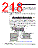
219 / 282 page  219 7728D–AVR–07/09 ATtiny87/ATtiny167 20.2.1 Store Program Memory Control and Status Register – SPMCSR The Store Program Memory Control and Status Register contains the control bits needed to control the Boot Loader operations. • Bit 7 – Res: Reserved Bit This bit is a reserved bit in the ATtiny87/167 and will always read as zero. • Bit 6 – RWWSB: Read-While-Write Section Busy This bit is for compatibility with devices supporting Read-While-Write. It will always read as zero in ATtiny87/167. • Bit 5 – SIGRD: Signature Row Read If this bit is written to one at the same time as SPMEN, the next LPM instruction within three clock cycles will read a byte from the signature row into the destination register. See ”Reading the Signature Row from Software” on page 221. for details. An SPM instruction within four cycles after SIGRD and SPMEN are set will have no effect. • Bit 4 – CTPB: Clear Temporary Page Buffer If the CTPB bit is written while filling the temporary page buffer, the temporary page buffer will be cleared and the data will be lost. • Bit 3 – RFLB: Read Fuse and Lock Bits An LPM instruction within three cycles after RFLB and SPMEN are set in the SPMCSR Regis- ter, will read either the Lock bits or the Fuse bits (depending on Z0 in the Z-pointer) into the destination register. See ”Reading the Fuse and Lock Bits from Software” on page 220. for details. • Bit 2 – PGWRT: Page Write If this bit is written to one at the same time as SPMEN, the next SPM instruction within four clock cycles executes Page Write, with the data stored in the temporary buffer. The page address is taken from the high part of the Z-pointer. The data in R1 and R0 are ignored. The PGWRT bit will auto-clear upon completion of a Page Write, or if no SPM instruction is exe- cuted within four clock cycles. The CPU is halted during the entire Page Write operation. • Bit 1 – PGERS: Page Erase If this bit is written to one at the same time as SPMEN, the next SPM instruction within four clock cycles executes Page Erase. The page address is taken from the high part of the Zpointer. The data in R1 and R0 are ignored. The PGERS bit will auto-clear upon completion of a Page Erase, or if no SPM instruction is executed within four clock cycles. The CPU is halted during the entire Page Write operation. Bit 765 4321 0 – RWWSB SIGRD CTPB RFLB PGWRT PGERS SPMEN SPMCSR Read/Write R R R R/W R/W R/W R/W R/W Initial Value 000 0000 0 |
|
ссылки URL |
| Вашему бизинису помогли Аллдатащит? [ DONATE ] |
Что такое Аллдатащит | реклама | контакт | Конфиденциальность | Ссылка на техническое описание | обмен ссыками | поиск по производителю All Rights Reserved©Alldatasheet.com |
| Russian : Alldatasheetru.com | Korean : Alldatasheet.co.kr | Spanish : Alldatasheet.es | French : Alldatasheet.fr | Italian : Alldatasheetit.com Portuguese : Alldatasheetpt.com | Polish : Alldatasheet.pl | Vietnamese : Alldatasheet.vn Indian : Alldatasheet.in | Mexican : Alldatasheet.com.mx | British : Alldatasheet.co.uk | New Zealand : Alldatasheet.co.nz |
|
Family Site : ic2ic.com |
icmetro.com |
 Russian ▼
 English
 Chinese
 German
 Japanese
 Russian
 Korean
 Spanish
 French
 Italian
 Portuguese
 Polish
 Vietnamese
 Indian
 Mexican
 British
 New Zealand