|
поискавой системы для электроныых деталей |
|
|
поискавой системы для электроныых деталей |
|
PIC16F684 датащи(PDF) 15 Page - Microchip Technology |
|
|
|||||||||||||||||||||||||||||
PIC16F684 датащи(HTML) 15 Page - Microchip Technology |
|
|
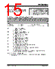
15 / 192 page  © 2007 Microchip Technology Inc. DS41202F-page 13 PIC16F684 2.2.2.3 INTCON Register The INTCON register is a readable and writable register, which contains the various enable and flag bits for TMR0 register overflow, PORTA change and external RA2/INT pin interrupts. Note: Interrupt flag bits are set when an interrupt condition occurs, regardless of the state of its corresponding enable bit or the global enable bit, GIE of the INTCON register. User software should ensure the appropriate interrupt flag bits are clear prior to enabling an interrupt. REGISTER 2-3: INTCON: INTERRUPT CONTROL REGISTER R/W-0 R/W-0 R/W-0 R/W-0 R/W-0 R/W-0 R/W-0 R/W-0 GIE PEIE T0IE INTE RAIE T0IF INTF RAIF bit 7 bit 0 Legend: R = Readable bit W = Writable bit U = Unimplemented bit, read as ‘0’ -n = Value at POR ‘1’ = Bit is set ‘0’ = Bit is cleared x = Bit is unknown bit 7 GIE: Global Interrupt Enable bit 1 = Enables all unmasked interrupts 0 = Disables all interrupts bit 6 PEIE: Peripheral Interrupt Enable bit 1 = Enables all unmasked peripheral interrupts 0 = Disables all peripheral interrupts bit 5 T0IE: Timer0 Overflow Interrupt Enable bit 1 = Enables the Timer0 interrupt 0 = Disables the Timer0 interrupt bit 4 INTE: RA2/INT External Interrupt Enable bit 1 = Enables the RA2/INT external interrupt 0 = Disables the RA2/INT external interrupt bit 3 RAIE: PORTA Change Interrupt Enable bit(1) 1 = Enables the PORTA change interrupt 0 = Disables the PORTA change interrupt bit 2 T0IF: Timer0 Overflow Interrupt Flag bit(2) 1 = Timer0 register has overflowed (must be cleared in software) 0 = Timer0 register did not overflow bit 1 INTF: RA2/INT External Interrupt Flag bit 1 = The RA2/INT external interrupt occurred (must be cleared in software) 0 = The RA2/INT external interrupt did not occur bit 0 RAIF: PORTA Change Interrupt Flag bit 1 = When at least one of the PORTA <5:0> pins changed state (must be cleared in software) 0 = None of the PORTA <5:0> pins have changed state Note 1: IOCA register must also be enabled. 2: T0IF bit is set when TMR0 rolls over. TMR0 is unchanged on Reset and should be initialized before clearing T0IF bit. |
|
ссылки URL |
| Вашему бизинису помогли Аллдатащит? [ DONATE ] |
Что такое Аллдатащит | реклама | контакт | Конфиденциальность | Ссылка на техническое описание | обмен ссыками | поиск по производителю All Rights Reserved©Alldatasheet.com |
| Russian : Alldatasheetru.com | Korean : Alldatasheet.co.kr | Spanish : Alldatasheet.es | French : Alldatasheet.fr | Italian : Alldatasheetit.com Portuguese : Alldatasheetpt.com | Polish : Alldatasheet.pl | Vietnamese : Alldatasheet.vn Indian : Alldatasheet.in | Mexican : Alldatasheet.com.mx | British : Alldatasheet.co.uk | New Zealand : Alldatasheet.co.nz |
|
Family Site : ic2ic.com |
icmetro.com |
 Russian ▼
 English
 Chinese
 German
 Japanese
 Russian
 Korean
 Spanish
 French
 Italian
 Portuguese
 Polish
 Vietnamese
 Indian
 Mexican
 British
 New Zealand