|
поискавой системы для электроныых деталей |
|
|
поискавой системы для электроныых деталей |
|
PIC16F684 датащи(PDF) 23 Page - Microchip Technology |
|
|
|||||||||||||||||||||||||||||
PIC16F684 датащи(HTML) 23 Page - Microchip Technology |
|
|
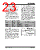
23 / 192 page  © 2007 Microchip Technology Inc. DS41202F-page 21 PIC16F684 3.3 Clock Source Modes Clock Source modes can be classified as external or internal. • External Clock modes rely on external circuitry for the clock source. Examples are: Oscillator mod- ules (EC mode), quartz crystal resonators or ceramic resonators (LP, XT and HS modes) and Resistor-Capacitor (RC) mode circuits. • Internal clock sources are contained internally within the Oscillator module. The Oscillator module has two internal oscillators: the 8 MHz High-Frequency Internal Oscillator (HFINTOSC) and the 31 kHz Low-Frequency Internal Oscillator (LFINTOSC). The system clock can be selected between external or internal clock sources via the System Clock Select (SCS) bit of the OSCCON register. See Section 3.6 “Clock Switching” for additional information. 3.4 External Clock Modes 3.4.1 OSCILLATOR START-UP TIMER (OST) If the Oscillator module is configured for LP, XT or HS modes, the Oscillator Start-up Timer (OST) counts 1024 oscillations from OSC1. This occurs following a Power-on Reset (POR) and when the Power-up Timer (PWRT) has expired (if configured), or a wake-up from Sleep. During this time, the program counter does not increment and program execution is suspended. The OST ensures that the oscillator circuit, using a quartz crystal resonator or ceramic resonator, has started and is providing a stable system clock to the Oscillator module. When switching between clock sources, a delay is required to allow the new clock to stabilize. These oscillator delays are shown in Table 3-1. In order to minimize latency between external oscillator start-up and code execution, the Two-Speed Clock Start-up mode can be selected (see Section 3.7 “Two-Speed Clock Start-up Mode”). TABLE 3-1: OSCILLATOR DELAY EXAMPLES 3.4.2 EC MODE The External Clock (EC) mode allows an externally generated logic level as the system clock source. When operating in this mode, an external clock source is connected to the OSC1 input and the OSC2 is available for general purpose I/O. Figure 3-2 shows the pin connections for EC mode. The Oscillator Start-up Timer (OST) is disabled when EC mode is selected. Therefore, there is no delay in operation after a Power-on Reset (POR) or wake-up from Sleep. Because the PIC MCU design is fully static, stopping the external clock input will have the effect of halting the device while leaving all data intact. Upon restarting the external clock, the device will resume operation as if no time had elapsed. FIGURE 3-2: EXTERNAL CLOCK (EC) MODE OPERATION Switch From Switch To Frequency Oscillator Delay Sleep/POR LFINTOSC HFINTOSC 31 kHz 125 kHz to 8 MHz Oscillator Warm-Up Delay (TWARM) Sleep/POR EC, RC DC – 20 MHz 2 cycles LFINTOSC (31 kHz) EC, RC DC – 20 MHz 1 cycle of each Sleep/POR LP, XT, HS 32 kHz to 20 MHz 1024 Clock Cycles (OST) LFINTOSC (31 kHz) HFINTOSC 125 kHz to 8 MHz 1 μs (approx.) OSC1/CLKIN OSC2/CLKOUT(1) I/O Clock from Ext. System PIC® MCU Note 1: Alternate pin functions are listed in the Section 1.0 “Device Overview”. |
|
ссылки URL |
| Вашему бизинису помогли Аллдатащит? [ DONATE ] |
Что такое Аллдатащит | реклама | контакт | Конфиденциальность | Ссылка на техническое описание | обмен ссыками | поиск по производителю All Rights Reserved©Alldatasheet.com |
| Russian : Alldatasheetru.com | Korean : Alldatasheet.co.kr | Spanish : Alldatasheet.es | French : Alldatasheet.fr | Italian : Alldatasheetit.com Portuguese : Alldatasheetpt.com | Polish : Alldatasheet.pl | Vietnamese : Alldatasheet.vn Indian : Alldatasheet.in | Mexican : Alldatasheet.com.mx | British : Alldatasheet.co.uk | New Zealand : Alldatasheet.co.nz |
|
Family Site : ic2ic.com |
icmetro.com |
 Russian ▼
 English
 Chinese
 German
 Japanese
 Russian
 Korean
 Spanish
 French
 Italian
 Portuguese
 Polish
 Vietnamese
 Indian
 Mexican
 British
 New Zealand