|
поискавой системы для электроныых деталей |
|
|
поискавой системы для электроныых деталей |
|
PIC16F684 датащи(PDF) 25 Page - Microchip Technology |
|
|
|||||||||||||||||||||||||||||
PIC16F684 датащи(HTML) 25 Page - Microchip Technology |
|
|
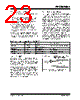
25 / 192 page  © 2007 Microchip Technology Inc. DS41202F-page 23 PIC16F684 3.4.4 EXTERNAL RC MODES The external Resistor-Capacitor (RC) modes support the use of an external RC circuit. This allows the designer maximum flexibility in frequency choice while keeping costs to a minimum when clock accuracy is not required. There are two modes: RC and RCIO. In RC mode, the RC circuit connects to OSC1. OSC2/CLKOUT outputs the RC oscillator frequency divided by 4. This signal may be used to provide a clock for external circuitry, synchronization, calibration, test or other application requirements. Figure 3-5 shows the external RC mode connections. FIGURE 3-5: EXTERNAL RC MODES In RCIO mode, the RC circuit is connected to OSC1. OSC2 becomes an additional general purpose I/O pin. The RC oscillator frequency is a function of the supply voltage, the resistor (REXT) and capacitor (CEXT) values and the operating temperature. Other factors affecting the oscillator frequency are: • threshold voltage variation • component tolerances • packaging variations in capacitance The user also needs to take into account variation due to tolerance of external RC components used. 3.5 Internal Clock Modes The Oscillator module has two independent, internal oscillators that can be configured or selected as the system clock source. 1. The HFINTOSC (High-Frequency Internal Oscillator) is factory calibrated and operates at 8 MHz. The frequency of the HFINTOSC can be user-adjusted via software using the OSCTUNE register (Register 3-2). 2. The LFINTOSC (Low-Frequency Internal Oscillator) is uncalibrated and operates at 31 kHz. The system clock speed can be selected via software using the Internal Oscillator Frequency Select bits IRCF<2:0> of the OSCCON register. The system clock can be selected between external or internal clock sources via the System Clock Selection (SCS) bit of the OSCCON register. See Section 3.6 “Clock Switching” for more information. 3.5.1 INTOSC AND INTOSCIO MODES The INTOSC and INTOSCIO modes configure the internal oscillators as the system clock source when the device is programmed using the oscillator selection or the FOSC<2:0> bits in the Configuration Word register (CONFIG). In INTOSC mode, OSC1/CLKIN is available for general purpose I/O. OSC2/CLKOUT outputs the selected internal oscillator frequency divided by 4. The CLKOUT signal may be used to provide a clock for external circuitry, synchronization, calibration, test or other application requirements. In INTOSCIO mode, OSC1/CLKIN and OSC2/CLKOUT are available for general purpose I/O. 3.5.2 HFINTOSC The High-Frequency Internal Oscillator (HFINTOSC) is a factory calibrated 8 MHz internal clock source. The frequency of the HFINTOSC can be altered via software using the OSCTUNE register (Register 3-2). The output of the HFINTOSC connects to a postscaler and multiplexer (see Figure 3-1). One of seven frequencies can be selected via software using the IRCF<2:0> bits of the OSCCON register. See Section 3.5.4 “Frequency Select Bits (IRCF)” for more information. The HFINTOSC is enabled by selecting any frequency between 8 MHz and 125 kHz by setting the IRCF<2:0> bits of the OSCCON register ≠ 000. Then, set the System Clock Source (SCS) bit of the OSCCON register to ‘1’ or enable Two-Speed Start-up by setting the IESO bit in the Configuration Word register (CONFIG) to ‘1’. The HF Internal Oscillator (HTS) bit of the OSCCON register indicates whether the HFINTOSC is stable or not. OSC2/CLKOUT(1) CEXT REXT PIC® MCU OSC1/CLKIN FOSC/4 or Internal Clock VDD VSS Recommended values: 10 k Ω ≤ REXT ≤ 100 kΩ, <3V 3 k Ω ≤ REXT ≤ 100 kΩ, 3-5V CEXT > 20 pF, 2-5V Note 1: Alternate pin functions are listed in Section 1.0 “Device Overview”. 2: Output depends upon RC or RCIO Clock mode. I/O(2) |
|
ссылки URL |
| Вашему бизинису помогли Аллдатащит? [ DONATE ] |
Что такое Аллдатащит | реклама | контакт | Конфиденциальность | Ссылка на техническое описание | обмен ссыками | поиск по производителю All Rights Reserved©Alldatasheet.com |
| Russian : Alldatasheetru.com | Korean : Alldatasheet.co.kr | Spanish : Alldatasheet.es | French : Alldatasheet.fr | Italian : Alldatasheetit.com Portuguese : Alldatasheetpt.com | Polish : Alldatasheet.pl | Vietnamese : Alldatasheet.vn Indian : Alldatasheet.in | Mexican : Alldatasheet.com.mx | British : Alldatasheet.co.uk | New Zealand : Alldatasheet.co.nz |
|
Family Site : ic2ic.com |
icmetro.com |
 Russian ▼
 English
 Chinese
 German
 Japanese
 Russian
 Korean
 Spanish
 French
 Italian
 Portuguese
 Polish
 Vietnamese
 Indian
 Mexican
 British
 New Zealand