|
поискавой системы для электроныых деталей |
|
|
поискавой системы для электроныых деталей |
|
PIC16F684 датащи(PDF) 86 Page - Microchip Technology |
|
|
|||||||||||||||||||||||||||||
PIC16F684 датащи(HTML) 86 Page - Microchip Technology |
|
|
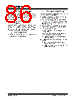
86 / 192 page  PIC16F684 DS41202F-page 84 © 2007 Microchip Technology Inc. 11.3.4 OPERATION IN SLEEP MODE In Sleep mode, the TMR2 register will not increment and the state of the module will not change. If the CCP1 pin is driving a value, it will continue to drive that value. When the device wakes up, TMR2 will continue from its previous state. 11.3.5 CHANGES IN SYSTEM CLOCK FREQUENCY The PWM frequency is derived from the system clock frequency. Any changes in the system clock frequency will result in changes to the PWM frequency. See Section 3.0 “Oscillator Module (With Fail-Safe Clock Monitor)” for additional details. 11.3.6 EFFECTS OF RESET Any Reset will force all ports to Input mode and the CCP registers to their Reset states. 11.3.7 SETUP FOR PWM OPERATION The following steps should be taken when configuring the CCP module for PWM operation: 1. Disable the PWM pin (CCP1) output driver by setting the associated TRIS bit. 2. Set the PWM period by loading the PR2 register. 3. Configure the CCP module for the PWM mode by loading the CCP1CON register with the appropriate values. 4. Set the PWM duty cycle by loading the CCPR1L register and CCP1 bits of the CCP1CON register. 5. Configure and start Timer2: • Clear the TMR2IF interrupt flag bit of the PIR1 register. • Set the Timer2 prescale value by loading the T2CKPS bits of the T2CON register. • Enable Timer2 by setting the TMR2ON bit of the T2CON register. 6. Enable PWM output after a new PWM cycle has started: • Wait until Timer2 overflows (TMR2IF bit of the PIR1 register is set). • Enable the CCP1 pin output driver by clearing the associated TRIS bit. |
|
ссылки URL |
| Вашему бизинису помогли Аллдатащит? [ DONATE ] |
Что такое Аллдатащит | реклама | контакт | Конфиденциальность | Ссылка на техническое описание | обмен ссыками | поиск по производителю All Rights Reserved©Alldatasheet.com |
| Russian : Alldatasheetru.com | Korean : Alldatasheet.co.kr | Spanish : Alldatasheet.es | French : Alldatasheet.fr | Italian : Alldatasheetit.com Portuguese : Alldatasheetpt.com | Polish : Alldatasheet.pl | Vietnamese : Alldatasheet.vn Indian : Alldatasheet.in | Mexican : Alldatasheet.com.mx | British : Alldatasheet.co.uk | New Zealand : Alldatasheet.co.nz |
|
Family Site : ic2ic.com |
icmetro.com |
 Russian ▼
 English
 Chinese
 German
 Japanese
 Russian
 Korean
 Spanish
 French
 Italian
 Portuguese
 Polish
 Vietnamese
 Indian
 Mexican
 British
 New Zealand