|
поискавой системы для электроныых деталей |
|
|
поискавой системы для электроныых деталей |
|
PIC16F684 датащи(PDF) 51 Page - Microchip Technology |
|
|
|||||||||||||||||||||||||||||
PIC16F684 датащи(HTML) 51 Page - Microchip Technology |
|
|
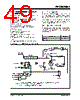
51 / 192 page  © 2007 Microchip Technology Inc. DS41202F-page 49 PIC16F684 6.6 Timer1 Gate Timer1 gate source is software configurable to be the T1G pin or the output of Comparator 2. This allows the device to directly time external events using T1G or analog events using Comparator 2. See the CMCON1 register (Register 8-2) for selecting the Timer1 gate source. This feature can simplify the software for a Delta-Sigma A/D converter and many other applications. For more information on Delta-Sigma A/D converters, see the Microchip web site (www.microchip.com). Timer1 gate can be inverted using the T1GINV bit of the T1CON register, whether it originates from the T1G pin or Comparator 2 output. This configures Timer1 to measure either the active-high or active-low time between events. 6.7 Timer1 Interrupt The Timer1 register pair (TMR1H:TMR1L) increments to FFFFh and rolls over to 0000h. When Timer1 rolls over, the Timer1 interrupt flag bit of the PIR1 register is set. To enable the interrupt on rollover, you must set these bits: • TMR1ON bit or the T1CON register • TMR1IE bit of the PIE1 register • PEIE bit of the INTCON register • GIE bit of the INTCON register The interrupt is cleared by clearing the TMR1IF bit in the Interrupt Service Routine. 6.8 Timer1 Operation During Sleep Timer1 can only operate during Sleep when setup in Asynchronous Counter mode. In this mode, an external crystal or clock source can be used to increment the counter. To set up the timer to wake the device: • TMR1ON bit of the T1CON register must be set • TMR1IE bit of the PIE1 register must be set • PEIE bit of the INTCON register must be set • T1SYNC bit of the T1CON register • TMR1CS bit of the T1CON register • T1OSCEN bit of the T1CON register (can be set) The device will wake-up on an overflow and execute the next instruction. If the GIE bit of the INTCON register is set, the device will call the Interrupt Service Routine (0004h). 6.9 ECCP Capture/Compare Time Base The ECCP module uses the TMR1H:TMR1L register pair as the time base when operating in Capture or Compare mode. In Capture mode, the value in the TMR1H:TMR1L register pair is copied into the CCPR1H:CCPR1L register pair on a configured event. In Compare mode, an event is triggered when the value CCPR1H:CCPR1L register pair matches the value in the TMR1H:TMR1L register pair. This event can be a Special Event Trigger. For more information, see Section 11.0 “Enhanced Capture/Compare/PWM (With Auto-Shutdown and Dead Band) Module”. 6.10 ECCP Special Event Trigger When the ECCP is configured to trigger a special event, the trigger will clear the TMR1H:TMR1L register pair. This special event does not cause a Timer1 interrupt. The ECCP module may still be configured to generate a ECCP interrupt. In this mode of operation, the CCPR1H:CCPR1L register pair effectively becomes the period register for Timer1. Timer1 should be synchronized to the FOSC to utilize the Special Event Trigger. Asynchronous operation of Timer1 can cause a Special Event Trigger to be missed. In the event that a write to TMR1H or TMR1L coincides with a Special Event Trigger from the ECCP, the write will take precedence. For more information, see Section 11.2.4 “Special Event Trigger”. 6.11 Comparator Synchronization The same clock used to increment Timer1 can also be used to synchronize the comparator output. This feature is enabled in the Comparator module. When using the comparator for Timer1 gate, the comparator output should be synchronized to Timer1. This ensures Timer1 does not miss an increment if the comparator changes. For more information, see Section 8.9 “Synchronizing Comparator C2 Output to Timer1”. Note: TMR1GE bit of the T1CON register must be set to use either T1G or C2OUT as the Timer1 gate source. See the CMCON1 register (Register 8-2) for more informa- tion on selecting the Timer1 gate source. Note: The TMR1H:TTMR1L register pair and the TMR1IF bit should be cleared before enabling interrupts. |
|
ссылки URL |
| Вашему бизинису помогли Аллдатащит? [ DONATE ] |
Что такое Аллдатащит | реклама | контакт | Конфиденциальность | Ссылка на техническое описание | обмен ссыками | поиск по производителю All Rights Reserved©Alldatasheet.com |
| Russian : Alldatasheetru.com | Korean : Alldatasheet.co.kr | Spanish : Alldatasheet.es | French : Alldatasheet.fr | Italian : Alldatasheetit.com Portuguese : Alldatasheetpt.com | Polish : Alldatasheet.pl | Vietnamese : Alldatasheet.vn Indian : Alldatasheet.in | Mexican : Alldatasheet.com.mx | British : Alldatasheet.co.uk | New Zealand : Alldatasheet.co.nz |
|
Family Site : ic2ic.com |
icmetro.com |
 Russian ▼
 English
 Chinese
 German
 Japanese
 Russian
 Korean
 Spanish
 French
 Italian
 Portuguese
 Polish
 Vietnamese
 Indian
 Mexican
 British
 New Zealand