|
поискавой системы для электроныых деталей |
|
|
поискавой системы для электроныых деталей |
|
PIC16F684 датащи(PDF) 27 Page - Microchip Technology |
|
|
|||||||||||||||||||||||||||||
PIC16F684 датащи(HTML) 27 Page - Microchip Technology |
|
|
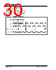
27 / 192 page  © 2007 Microchip Technology Inc. DS41202F-page 25 PIC16F684 3.5.3 LFINTOSC The Low-Frequency Internal Oscillator (LFINTOSC) is an uncalibrated 31 kHz internal clock source. The output of the LFINTOSC connects to a postscaler and multiplexer (see Figure 3-1). Select 31 kHz, via software, using the IRCF<2:0> bits of the OSCCON register. See Section 3.5.4 “Frequency Select Bits (IRCF)” for more information. The LFINTOSC is also the frequency for the Power-up Timer (PWRT), Watchdog Timer (WDT) and Fail-Safe Clock Monitor (FSCM). The LFINTOSC is enabled by selecting 31 kHz (IRCF<2:0> bits of the OSCCON register = 000) as the system clock source (SCS bit of the OSCCON register = 1), or when any of the following are enabled: • Two-Speed Start-up IESO bit of the Configuration Word register = 1 and IRCF<2:0> bits of the OSCCON register = 000 • Power-up Timer (PWRT) • Watchdog Timer (WDT) • Fail-Safe Clock Monitor (FSCM) The LF Internal Oscillator (LTS) bit of the OSCCON register indicates whether the LFINTOSC is stable or not. 3.5.4 FREQUENCY SELECT BITS (IRCF) The output of the 8 MHz HFINTOSC and 31 kHz LFINTOSC connects to a postscaler and multiplexer (see Figure 3-1). The Internal Oscillator Frequency Select bits IRCF<2:0> of the OSCCON register select the frequency output of the internal oscillators. One of eight frequencies can be selected via software: •8 MHz • 4 MHz (Default after Reset) •2 MHz •1 MHz • 500 kHz • 250 kHz • 125 kHz • 31 kHz (LFINTOSC) 3.5.5 HFINTOSC AND LFINTOSC CLOCK SWITCH TIMING When switching between the LFINTOSC and the HFINTOSC, the new oscillator may already be shut down to save power (see Figure 3-6). If this is the case, there is a delay after the IRCF<2:0> bits of the OSCCON register are modified before the frequency selection takes place. The LTS and HTS bits of the OSCCON register will reflect the current active status of the LFINTOSC and HFINTOSC oscillators. The timing of a frequency selection is as follows: 1. IRCF<2:0> bits of the OSCCON register are modified. 2. If the new clock is shut down, a clock start-up delay is started. 3. Clock switch circuitry waits for a falling edge of the current clock. 4. CLKOUT is held low and the clock switch circuitry waits for a rising edge in the new clock. 5. CLKOUT is now connected with the new clock. LTS and HTS bits of the OSCCON register are updated as required. 6. Clock switch is complete. See Figure 3-1 for more details. If the internal oscillator speed selected is between 8 MHz and 125 kHz, there is no start-up delay before the new frequency is selected. This is because the old and new frequencies are derived from the HFINTOSC via the postscaler and multiplexer. Start-up delay specifications are located in the oscillator tables of Section 15.0 “Electrical Specifications”. Note: Following any Reset, the IRCF<2:0> bits of the OSCCON register are set to ‘110’ and the frequency selection is set to 4 MHz. The user can modify the IRCF bits to select a different frequency. |
|
ссылки URL |
| Вашему бизинису помогли Аллдатащит? [ DONATE ] |
Что такое Аллдатащит | реклама | контакт | Конфиденциальность | Ссылка на техническое описание | обмен ссыками | поиск по производителю All Rights Reserved©Alldatasheet.com |
| Russian : Alldatasheetru.com | Korean : Alldatasheet.co.kr | Spanish : Alldatasheet.es | French : Alldatasheet.fr | Italian : Alldatasheetit.com Portuguese : Alldatasheetpt.com | Polish : Alldatasheet.pl | Vietnamese : Alldatasheet.vn Indian : Alldatasheet.in | Mexican : Alldatasheet.com.mx | British : Alldatasheet.co.uk | New Zealand : Alldatasheet.co.nz |
|
Family Site : ic2ic.com |
icmetro.com |
 Russian ▼
 English
 Chinese
 German
 Japanese
 Russian
 Korean
 Spanish
 French
 Italian
 Portuguese
 Polish
 Vietnamese
 Indian
 Mexican
 British
 New Zealand