|
поискавой системы для электроныых деталей |
|
|
поискавой системы для электроныых деталей |
|
PIC16F684 датащи(PDF) 82 Page - Microchip Technology |
|
|
|||||||||||||||||||||||||||||
PIC16F684 датащи(HTML) 82 Page - Microchip Technology |
|
|
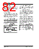
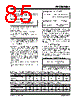
82 / 192 page  PIC16F684 DS41202F-page 80 © 2007 Microchip Technology Inc. 11.1 Capture Mode In Capture mode, CCPR1H:CCPR1L captures the 16-bit value of the TMR1 register when an event occurs on pin CCP1. An event is defined as one of the following and is configured by the CCP1M<3:0> bits of the CCP1CON register: • Every falling edge • Every rising edge • Every 4th rising edge • Every 16th rising edge When a capture is made, the Interrupt Request Flag bit CCP1IF of the PIR1 register is set. The interrupt flag must be cleared in software. If another capture occurs before the value in the CCPR1H, CCPR1L register pair is read, the old captured value is overwritten by the new captured value (see Figure 11-1). 11.1.1 CCP1 PIN CONFIGURATION In Capture mode, the CCP1 pin should be configured as an input by setting the associated TRIS control bit. FIGURE 11-1: CAPTURE MODE OPERATION BLOCK DIAGRAM 11.1.2 TIMER1 MODE SELECTION Timer1 must be running in Timer mode or Synchronized Counter mode for the CCP module to use the capture feature. In Asynchronous Counter mode, the capture operation may not work. 11.1.3 SOFTWARE INTERRUPT When the Capture mode is changed, a false capture interrupt may be generated. The user should keep the CCP1IE interrupt enable bit of the PIE1 register clear to avoid false interrupts. Additionally, the user should clear the CCP1IF interrupt flag bit of the PIR1 register following any change in operating mode. 11.1.4 CCP PRESCALER There are four prescaler settings specified by the CCP1M<3:0> bits of the CCP1CON register. Whenever the CCP module is turned off, or the CCP module is not in Capture mode, the prescaler counter is cleared. Any Reset will clear the prescaler counter. Switching from one capture prescaler to another does not clear the prescaler and may generate a false interrupt. To avoid this unexpected operation, turn the module off by clearing the CCP1CON register before changing the prescaler (see Example 11-1). EXAMPLE 11-1: CHANGING BETWEEN CAPTURE PRESCALERS Note: If the CCP1 pin is configured as an output, a write to the port can cause a capture condition. CCPR1H CCPR1L TMR1H TMR1L Set Flag bit CCP1IF (PIR1 register) Capture Enable CCP1CON<3:0> Prescaler ÷ 1, 4, 16 and Edge Detect pin CCP1 System Clock (FOSC) BANKSEL CCP1CON ;Set Bank bits to point ;to CCP1CON CLRF CCP1CON ;Turn CCP module off MOVLW NEW_CAPT_PS ;Load the W reg with ; the new prescaler ; move value and CCP ON MOVWF CCP1CON ;Load CCP1CON with this ; value |
|
ссылки URL |
| Вашему бизинису помогли Аллдатащит? [ DONATE ] |
Что такое Аллдатащит | реклама | контакт | Конфиденциальность | Ссылка на техническое описание | обмен ссыками | поиск по производителю All Rights Reserved©Alldatasheet.com |
| Russian : Alldatasheetru.com | Korean : Alldatasheet.co.kr | Spanish : Alldatasheet.es | French : Alldatasheet.fr | Italian : Alldatasheetit.com Portuguese : Alldatasheetpt.com | Polish : Alldatasheet.pl | Vietnamese : Alldatasheet.vn Indian : Alldatasheet.in | Mexican : Alldatasheet.com.mx | British : Alldatasheet.co.uk | New Zealand : Alldatasheet.co.nz |
|
Family Site : ic2ic.com |
icmetro.com |
 Russian ▼
 English
 Chinese
 German
 Japanese
 Russian
 Korean
 Spanish
 French
 Italian
 Portuguese
 Polish
 Vietnamese
 Indian
 Mexican
 British
 New Zealand