|
поискавой системы для электроныых деталей |
|
|
поискавой системы для электроныых деталей |
|
PIC16F684 датащи(PDF) 116 Page - Microchip Technology |
|
|
|||||||||||||||||||||||||||||
PIC16F684 датащи(HTML) 116 Page - Microchip Technology |
|
|
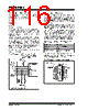
116 / 192 page  PIC16F684 DS41202F-page 114 © 2007 Microchip Technology Inc. 12.10 In-Circuit Serial Programming The PIC16F684 microcontrollers can be serially programmed while in the end application circuit. This is simply done with five connections for: •clock •data • power • ground • programming voltage This allows customers to manufacture boards with unprogrammed devices and then program the micro- controller just before shipping the product. This also allows the most recent firmware or a custom firmware to be programmed. The device is placed into a Program/Verify mode by holding the RA0 and RA1 pins low, while raising the MCLR (VPP) pin from VIL to VIHH. See the “PIC12F6XX/16F6XX Memory Programming Specification” (DS41204) for more information. RA0 becomes the programming data and RA1 becomes the programming clock. Both RA0 and RA1 are Schmitt Trigger inputs in Program/Verify mode. A typical In-Circuit Serial Programming connection is shown in Figure 12-11. FIGURE 12-11: TYPICAL IN-CIRCUIT SERIAL PROGRAMMING CONNECTION 12.11 In-Circuit Debugger Since in-circuit debugging requires access to three pins, MPLAB® ICD 2 development with a 14-pin device is not practical. A special 20-pin PIC16F684 ICD device is used with MPLAB ICD 2 to provide separate clock, data and MCLR pins and frees all normally available pins to the user. A special debugging adapter allows the ICD device to be used in place of a PIC16F684 device. The debugging adapter is the only source of the ICD device. When the ICD pin on the PIC16F684 ICD device is held low, the In-Circuit Debugger functionality is enabled. This function allows simple debugging functions when used with MPLAB ICD 2. When the microcontroller has this feature enabled, some of the resources are not available for general use. Table 12-9 shows which features are consumed by the background debugger. TABLE 12-9: DEBUGGER RESOURCES For more information, see “MPLAB® ICD 2 In-Circuit Debugger User’s Guide” (DS51331), available on Microchip’s web site (www.microchip.com). FIGURE 12-12: 20-PIN ICD PINOUT External Connector Signals To Normal Connections To Normal Connections PIC16F684 VDD VSS MCLR/VPP/RA3 RA1 RA0 +5V 0V VPP CLK Data I/O * * * * * Isolation devices (as required) Resource Description I/O pins ICDCLK, ICDDATA Stack 1 level Program Memory Address 0h must be NOP 700h-7FFh 20-Pin PDIP In-Circuit Debug Device NC ICDMCLR/VPP VDD RA5 RA4 RA3 ICDCLK ICDDATA Vss RA0 ICD NC RA1 RA2 RC5 RC4 RC3 RC0 RC1 RC2 1 2 3 4 5 6 7 8 9 10 20 19 18 17 16 15 14 13 12 11 |
|
ссылки URL |
| Вашему бизинису помогли Аллдатащит? [ DONATE ] |
Что такое Аллдатащит | реклама | контакт | Конфиденциальность | Ссылка на техническое описание | обмен ссыками | поиск по производителю All Rights Reserved©Alldatasheet.com |
| Russian : Alldatasheetru.com | Korean : Alldatasheet.co.kr | Spanish : Alldatasheet.es | French : Alldatasheet.fr | Italian : Alldatasheetit.com Portuguese : Alldatasheetpt.com | Polish : Alldatasheet.pl | Vietnamese : Alldatasheet.vn Indian : Alldatasheet.in | Mexican : Alldatasheet.com.mx | British : Alldatasheet.co.uk | New Zealand : Alldatasheet.co.nz |
|
Family Site : ic2ic.com |
icmetro.com |
 Russian ▼
 English
 Chinese
 German
 Japanese
 Russian
 Korean
 Spanish
 French
 Italian
 Portuguese
 Polish
 Vietnamese
 Indian
 Mexican
 British
 New Zealand