|
поискавой системы для электроныых деталей |
|
|
поискавой системы для электроныых деталей |
|
PIC16F627A датащи(PDF) 103 Page - Microchip Technology |
|
|
|||||||||||||||||||||||||||||
PIC16F627A датащи(HTML) 103 Page - Microchip Technology |
|
|
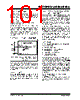
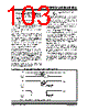
103 / 180 page  © 2005 Microchip Technology Inc. DS40044D-page 101 PIC16F627A/628A/648A 14.4 Power-on Reset (POR), Power-up Timer (PWRT), Oscillator Start-up Timer (OST) and Brown-out Reset (BOR) 14.4.1 POWER-ON RESET (POR) The on-chip POR holds the part in Reset until a VDD rise is detected (in the range of 1.2-1.7V). A maxi- mum rise time for VDD is required. See Section 17.0 “Electrical Specifications” for details. The POR circuit does not produce an internal Reset when VDD declines. When the device starts normal operation (exits the Reset condition), device operating parameters (voltage, frequency, temperature, etc.) must be met to ensure proper operation. If these conditions are not met, the device must be held in Reset via MCLR, BOR or PWRT until the operating conditions are met. For additional information, refer to Application Note AN607 “Power-up Trouble Shooting” (DS00607). 14.4.2 POWER-UP TIMER (PWRT) The PWRT provides a fixed 72 ms (nominal) time out on power-up (POR) or if enabled from a Brown-out Reset. The PWRT operates on an internal RC oscilla- tor. The chip is kept in Reset as long as PWRT is active. The PWRT delay allows the VDD to rise to an accept- able level. A configuration bit, PWRTE can disable (if set) or enable (if cleared or programmed) the PWRT. It is recommended that the PWRT be enabled when Brown-out Reset is enabled. The power-up time delay will vary from chip-to-chip and due to VDD, temperature and process variation. See DC parameters Table 17-7 for details. 14.4.3 OSCILLATOR START-UP TIMER (OST) The OST provides a 1024 oscillator cycle (from OSC1 input) delay after the PWRT delay is over. Program execution will not start until the OST time out is complete. This ensures that the crystal oscillator or resonator has started and stabilized. The OST time out is invoked only for XT, LP and HS modes and only on Power-on Reset or wake-up from Sleep. See Table 17-7. 14.4.4 BROWN-OUT RESET (BOR) The PIC16F627A/628A/648A have on-chip BOR circuitry. A configuration bit, BOREN, can disable (if clear/programmed) or enable (if set) the BOR circuitry. If VDD falls below VBOR for longer than TBOR, the brown-out situation will reset the chip. A Reset is not assured if VDD falls below VBOR for shorter than TBOR. VBOR and TBOR are defined in Table 17-2 and Table 17-7, respectively. On any Reset (Power-on, Brown-out, Watchdog, etc.), the chip will remain in Reset until VDD rises above VBOR (see Figure 14-7). The Power-up Timer will now be invoked, if enabled, and will keep the chip in Reset an additional 72 ms. If VDD drops below VBOR while the Power-up Timer is running, the chip will go back into a Brown-out Reset and the Power-up Timer will be re-initialized. Once VDD rises above VBOR, the Power-Up Timer will execute a 72 ms Reset. Figure 14-7 shows typical brown-out situations. FIGURE 14-7: BROWN-OUT SITUATIONS WITH PWRT ENABLED 72 ms VBOR VDD Internal Reset VBOR VDD Internal Reset 72 ms <72 ms 72 ms VBOR VDD Internal Reset ≥ TBOR Note: 72 ms delay only if PWRTE bit is programmed to ‘0’. |
|
ссылки URL |
| Вашему бизинису помогли Аллдатащит? [ DONATE ] |
Что такое Аллдатащит | реклама | контакт | Конфиденциальность | Ссылка на техническое описание | обмен ссыками | поиск по производителю All Rights Reserved©Alldatasheet.com |
| Russian : Alldatasheetru.com | Korean : Alldatasheet.co.kr | Spanish : Alldatasheet.es | French : Alldatasheet.fr | Italian : Alldatasheetit.com Portuguese : Alldatasheetpt.com | Polish : Alldatasheet.pl | Vietnamese : Alldatasheet.vn Indian : Alldatasheet.in | Mexican : Alldatasheet.com.mx | British : Alldatasheet.co.uk | New Zealand : Alldatasheet.co.nz |
|
Family Site : ic2ic.com |
icmetro.com |
 Russian ▼
 English
 Chinese
 German
 Japanese
 Russian
 Korean
 Spanish
 French
 Italian
 Portuguese
 Polish
 Vietnamese
 Indian
 Mexican
 British
 New Zealand