|
поискавой системы для электроныых деталей |
|
|
поискавой системы для электроныых деталей |
|
TC_LAB датащи(PDF) 13 Page - Wavelength Electronics, Inc. |
|
|
|||||||||||||||||||||||||||||
TC_LAB датащи(HTML) 13 Page - Wavelength Electronics, Inc. |
|
|
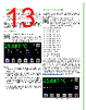
13 / 29 page  13 TURN ON THE POWER 1. Press the Power switch on the back panel to the | position. The front panel power button light slowly pulses. 2. Press the Power button on the front panel, the button illuminates, touchscreen is activated, and the Control Screen is active. NOTE: Turning off front Power button powers down the application electronics and puts the unit into standby mode. Turning off rear Power switch powers down all electronics and some settings return to factory default. SET LIMITS 1. Press to access the Limit Screen. 2. Press + Limit Current, - Limit Current, Max Temp, and/or Min Temp values and rotate the adjustment knob to change each value. The instrument will beep when set. Figure 15. Limit Screen NOTES: • The Limit Currents should not exceed the damage current threshold of the thermoelectric. To operate a resistive heater, set one limit to OFF. • The Max Temp and Min Temp can be set. If the actual sensor temperature exceeds these limits, this status is reported remotely so the user can take action. • A TTL signal is sent from the LD Shutdown BNC to trigger an interlock in a laser diode or QCL driver, if the actual temperature exceeds the limit(s) specified. The factory default polarity is ACTIVE HI. The polarity can be changed through remote commands. • The laser shutdown signal requires that a BNC to BNC cable is installed between the LD Shutdown on the TC LAB and the Active Lock on the QCL LAB. SELECT A SENSOR The sensor choice determines the sensor voltage to temperature relationship and which sensor pins are monitored on the 15+2 D-SUB. 1. Press to access the Sensor Screen. 2. Press the blue sensor name and turn the adjustment knob to cycle through the factory default sensor types or any user-defined sensors that were defined remotely. The factory default sensors are: • Thermistor, 5 kΩ 10 µA • Thermistor, 5 kΩ 100 µA • Thermistor, 10 kΩ 10 µA • Thermistor, 10 kΩ 100 µA • Thermistor, 20 kΩ 10 µA • Thermistor, 20 kΩ 100 µA • Thermistor, 50 kΩ 10 µA • Thermistor, 50 kΩ 100 µA • Thermistor, 100 kΩ 10 µA • RTD 2-wire, 100 Ω DIN • RTD 2-wire, 1 kΩ DIN • Linear IC Voltage Sensor • Linear IC Current Sensor The thermistor name includes the resistance at 25°C and the bias current base selection. See the thermistor datasheets for the resistance vs. temperature charts and Steinhart-Hart coefficients. The TC LAB auto-ranges the bias current by default. The current level in the sensor name merely defines the temperature range over which the sensor is calibrated. A fixed, non-volatile bias current can be configured with a custom sensor using remote command CONST:THERM with Firmware Versions 1.99 and 2.01 and later. See the LAB Series Command Set User Guide for more details. Figure 16. Sensor Screen |
|
ссылки URL |
| Вашему бизинису помогли Аллдатащит? [ DONATE ] |
Что такое Аллдатащит | реклама | контакт | Конфиденциальность | Ссылка на техническое описание | обмен ссыками | поиск по производителю All Rights Reserved©Alldatasheet.com |
| Russian : Alldatasheetru.com | Korean : Alldatasheet.co.kr | Spanish : Alldatasheet.es | French : Alldatasheet.fr | Italian : Alldatasheetit.com Portuguese : Alldatasheetpt.com | Polish : Alldatasheet.pl | Vietnamese : Alldatasheet.vn Indian : Alldatasheet.in | Mexican : Alldatasheet.com.mx | British : Alldatasheet.co.uk | New Zealand : Alldatasheet.co.nz |
|
Family Site : ic2ic.com |
icmetro.com |
 Russian ▼
 English
 Chinese
 German
 Japanese
 Russian
 Korean
 Spanish
 French
 Italian
 Portuguese
 Polish
 Vietnamese
 Indian
 Mexican
 British
 New Zealand