|
поискавой системы для электроныых деталей |
|
|
поискавой системы для электроныых деталей |
|
TC_LAB датащи(PDF) 16 Page - Wavelength Electronics, Inc. |
|
|
|||||||||||||||||||||||||||||
TC_LAB датащи(HTML) 16 Page - Wavelength Electronics, Inc. |
|
|
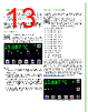
16 / 29 page  16 INTELLITUNE: INTELLIGENT AUTOTUNE IntelliTune adjusts the PID coefficients, as well as the voltage limit. 1. Turn off the output current. 2. On the Control Screen, press Tune mode to choose either Setpoint Response or Disturbance Rejection. Setpoint Response: This setting has a fast time to temperature and will overshoot. Disturbance Rejection: This setting has a quick return to setpoint after stability is reached. It is best for pulsing laser or active loads, or if ambient temperature fluctuates. Manual Tuning: Turns IntelliTune off. Figure 24. Control Screen 3. On the Limits screen, set Max/Min Temperature Limits. 4. Adjust the setpoint off ambient temperature by about 5ºC. 5. Make sure the setpoint will not cause a sensor bias current change by choosing a setpoint between 0.25 to 12.075 V. The scan is completed at a single bias current level. For 10 kΩ thermistors the troublesome temperatures are around -23ºC and 5ºC. For 50 kΩ thermistors, the troublesome temperatures are around 7ºC and 40ºC. 6. Press to start a characterization scan. NOTES: • The process takes three sweeps and can take several minutes. The “note” icon fills with red to indicate a scan is in progress. If any portion of the icon is red and you want to stop the process, press the “note” icon to abort the session. If the session is aborted, the PID coefficients revert to the previously used coefficients. • When the characterization process is complete, the new PID coefficients display and the icon reverts to green. • Tune only in temperature mode. Resistance mode is not supported. • A fixed, non-volatile bias current can be configured with a custom sensor using remote command CONST:THERM with Firmware Versions 1.99 and 2.01 and later. See the LAB Series Command Set User Guide for more details. SCAN THE TEMPERATURE 1. On the Control Screen, press to access the Temperature Scan Screen. 2. Press the Start Temp value to select the temperature at which to start the scan. Turn the adjustment knob to change it. 3. Press the Stop Temp value to select the temperature at which to stop the scan. 4. Press the Step Size value to select the temperature interval at which to take a measurement. 5. Press the Time Interval value to select the amount of time to allow the temperature to settle. 6. Insert the USB flash drive in the USB DATA slot on the front panel. 7. Press the Start Scan button to start the scan. When finished, data is saved to the USB flash drive with the filename tcscanxx.txt, where xx starts at 00 and increments. To stop mid-scan, press the red Stop Scan button. Any data collected during the aborted scan is saved to the USB flash drive. Figure 23. Scan Screen The tolerance window can be very useful during a scan. Change the time interval to STABLE by rotating the knob counter clockwise. When the temperature reaches the setpoint ± the tolerance window, a datapoint is recorded and the instrument increments the setpoint to the next indicated value. Ideally, the tolerance should be set very tight, much less than the scan step. Time Offset, Setpoint, Actual Temp, Sensor Voltage, TE Current, and TE Voltage are stored to the data file. Exiting the Scan screen aborts the scan. After the scan is complete, the current remains enabled and at the final scan setpoint. To trigger a datapoint from another instrument at a given temperature, use the TTL TempStable output or the remote TEC Condition Register In Tolerance bit to trigger the measurement. NOTE: Scan only in temperature mode. Resistance mode is not supported. |
|
ссылки URL |
| Вашему бизинису помогли Аллдатащит? [ DONATE ] |
Что такое Аллдатащит | реклама | контакт | Конфиденциальность | Ссылка на техническое описание | обмен ссыками | поиск по производителю All Rights Reserved©Alldatasheet.com |
| Russian : Alldatasheetru.com | Korean : Alldatasheet.co.kr | Spanish : Alldatasheet.es | French : Alldatasheet.fr | Italian : Alldatasheetit.com Portuguese : Alldatasheetpt.com | Polish : Alldatasheet.pl | Vietnamese : Alldatasheet.vn Indian : Alldatasheet.in | Mexican : Alldatasheet.com.mx | British : Alldatasheet.co.uk | New Zealand : Alldatasheet.co.nz |
|
Family Site : ic2ic.com |
icmetro.com |
 Russian ▼
 English
 Chinese
 German
 Japanese
 Russian
 Korean
 Spanish
 French
 Italian
 Portuguese
 Polish
 Vietnamese
 Indian
 Mexican
 British
 New Zealand