|
поискавой системы для электроныых деталей |
|
|
поискавой системы для электроныых деталей |
|
ADF4252BCPZ-R7 датащи(PDF) 25 Page - Analog Devices |
|
|
|||||||||||||||||||||||||||||
ADF4252BCPZ-R7 датащи(HTML) 25 Page - Analog Devices |
|
|
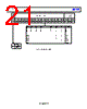
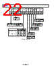
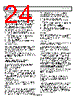
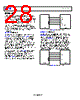
25 / 30 page  Data Sheet ADF4252 Rev. E | Page 25 of 30 IF B and IF A Counters The IF A and IF B counters, in conjunction with the dual- modulus prescaler, make it possible to generate output frequencies that are spaced only by the reference frequency (REFIN) divided by R. The equation for the IFOUT VCO frequency is given in Equation 2. IF R DIVIDER REGISTER (ADDRESS R5) With Bits[2:0] of R5 set to 101, the on-chip IF R divider register is programmed. Figure 40 shows the input data format for programming this register. IF REFIN Doubler Setting this bit to 0 feeds the REFIN signal directly to the 15-bit IF R counter. Setting this bit to 1 multiplies the REFIN frequency by a factor of 2 before feeding into the 15-bit IF R counter. 15-Bit IF R Counter The 15-bit IF R counter allows the input reference frequency (REFIN) to be divided down to produce the reference clock to the IF phase frequency detector (PFD). Division ratios from 1 to 32,767 are allowed. IF CONTROL REGISTER (ADDRESS R6) With Bits[2:0] of R6 set to 110, the on-chip IF control register is programmed. Figure 41 shows the input data format for programming this register. Upon initialization, DB15 to DB11 must all be set to 0. IF Counter Reset DB3 is the IF counter reset bit for the ADF4252. When this bit is 1, the IF synthesizer counters are held in reset. For normal operation, this bit must be 0. IF Charge Pump Three-State This bit puts the IF charge pump into three-state mode when programmed to a 1. It must be set to 0 for normal operation. IF Power-Down DB5 on the ADF4252 provides the programmable power-down mode. Setting this bit to a 1 performs a power-down on the IF section. Setting this bit to 0 returns the section to normal operation. While in software power-down, the device retains all information in its registers. Only when supplies are removed are the register contents lost. When a power-down is activated, the following events occur: 1. All active IF dc current paths are removed. 2. The IF synthesizer counters are forced to their load state conditions. 3. The IF charge pump is forced into three-state mode. 4. The IF digital lock detect circuitry is reset. 5. The IFIN input is debiased. 6. The input register remains active and capable of loading and latching data. IF Phase Detector Polarity DB7 in the ADF4252 sets the IF phase detector polarity. When the VCO characteristics are positive, this bit must be set to 1. When VCO characteristics are negative, this bit must be set to 0. IF Charge Pump Current Setting DB8, DB9, and DB10 set the IF charge pump current setting. These bits must be set to whatever charge pump current the loop filter has been designed with (see Figure 39). IF Test Modes These bits must be set to 00 for normal operation. RF Phase Resync Setting the phase resync bits (Bit 15, Bit 14, Bit 11) to 111 enables the phase resync feature. With a fractional modulus of M, a fractional-N PLL can settle with any one of (2 × π)/M valid phase offsets with respect to the reference input. This is different than integer-N (where the RF output always settles to the same static phase offset with respect to the input reference, which is zero ideally) but does not matter in most applications where all that is required is consistent frequency lock. For applications where a consistent phase relationship between the output and reference is required (that is, digital beamforming), the ADF4252 fractional-N synthesizer can be used with the phase resync feature enabled. This ensures that if the user programs the PLL to jump from Frequency (and Phase) A to Frequency (and Phase) B and back again to Frequency A, the PLL returns to the original phase (Phase A). When enabled, phase resync activates every time the user programs the R0 or R1 register to set a new output frequency. However, if a cycle slip occurs in the settling transient after the phase re-resync operation, the phase resync is lost. This can be avoided by delaying the resync activation until the locking transient is close to its final frequency. In the IF R divider register, Bits[17:3] of R5 are used to set a time interval from when the new channel is programmed to the time the resync is activated. Although the time interval resolution available from the 15-bit IF R register is one REFIN clock cycle, IF R must be programmed to be a value that is an integer multiple of the programmed MOD value to set a time interval that is at least as long as the lock time of the RF PLL loop. For example, if REFIN = 26 MHz, MOD = 130 to give 200 kHz output steps (fRES), and the RF loop has a settling time of 150 μs, then IF_R must be programmed to 3900, as follows: 26 MHz × 150 μs = 3900 Note that if it is required to use the IF synthesizer with phase resync enabled on the RF synth, the IF synth must operate with a PFD frequency of 26 MHz/3900. |
|
ссылки URL |
| Вашему бизинису помогли Аллдатащит? [ DONATE ] |
Что такое Аллдатащит | реклама | контакт | Конфиденциальность | Ссылка на техническое описание | обмен ссыками | поиск по производителю All Rights Reserved©Alldatasheet.com |
| Russian : Alldatasheetru.com | Korean : Alldatasheet.co.kr | Spanish : Alldatasheet.es | French : Alldatasheet.fr | Italian : Alldatasheetit.com Portuguese : Alldatasheetpt.com | Polish : Alldatasheet.pl | Vietnamese : Alldatasheet.vn Indian : Alldatasheet.in | Mexican : Alldatasheet.com.mx | British : Alldatasheet.co.uk | New Zealand : Alldatasheet.co.nz |
|
Family Site : ic2ic.com |
icmetro.com |
 Russian ▼
 English
 Chinese
 German
 Japanese
 Russian
 Korean
 Spanish
 French
 Italian
 Portuguese
 Polish
 Vietnamese
 Indian
 Mexican
 British
 New Zealand