|
поискавой системы для электроныых деталей |
|
|
поискавой системы для электроныых деталей |
|
MCP631 датащи(PDF) 24 Page - Microchip Technology |
|
|
|||||||||||||||||||||||||||||
MCP631 датащи(HTML) 24 Page - Microchip Technology |
|
|
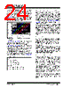
24 / 42 page  MCP631/2/3/5 DS22197A-page 24 © 2009 Microchip Technology Inc. CN and RN form a low-pass filter that affects the signal at VP. This filter has a single real pole at 1/(2πRNCN). The largest value of RF that should be used depends on noise gain (see GN in Section 4.3.1 “Capacitive Loads”), CG and the open-loop gain’s phase shift. Figure 4-9 shows the maximum recommended RF for several CG values. Some applications may modify these values to reduce either output loading or gain peaking (step response overshoot). FIGURE 4-9: Maximum Recommended RF vs. Gain. Figure 2-34 and Figure 2-35 show the small signal and large signal step responses at G = +1 V/V. The unity gain buffer usually has RF =0Ω and RG open. Figure 2-36 and Figure 2-37 show the small signal and large signal step responses at G = -1 V/V. Since the noise gain is 2 V/V and CG ≈ 10 pF, the resistors were chosen to be RF =RG =1kΩ and RN = 500Ω. It is also possible to add a capacitor (CF) in parallel with RF to compensate for the de-stabilizing effect of CG. This makes it possible to use larger values of RF. The conditions for stability are summarized in Equation 4-6. EQUATION 4-6: 4.4 MCP633 and MCP635 Chip Select The MCP633 is a single amplifier with Chip Select (CS). When CS is pulled high, the supply current drops to 1 µA (typical) and flows through the CS pin to VSS. When this happens, the amplifier output is put into a high-impedance state. By pulling CS low, the amplifier is enabled. The CS pin has an internal 5 M Ω (typical) pulldown resistor connected to VSS, so it will go low if the CS pin is left floating. Figure 1-1, Figure 2-42 and Figure 2-43 show the output voltage and supply current response to a CS pulse. The MCP635 is a dual amplifier with two CS pins; CSA controls op amp A and CSB controls op amp B. These op amps are controlled independently, with an enabled quiescent current (IQ) of 2.5 mA/amplifier (typical) and a disabled IQ of 1 µA/amplifier (typical). The IQ seen at the supply pins is the sum of the two op amps’ IQ; the typical value for the MCP635’s IQ will be 2 µA, 2.5 mA or 5 mA when there are 0, 1 or 2 amplifiers enabled, respectively. 4.5 Power Supply With this family of operational amplifiers, the power supply pin (VDD for single supply) should have a local bypass capacitor (i.e., 0.01 µF to 0.1 µF) within 2 mm for good high frequency performance. Surface mount, multilayer ceramic capacitors, or their equivalent, should be used. These op amps require a bulk capacitor (i.e., 2.2 µF or larger) within 50 mm to provide large, slow currents. Tantalum capacitors, or their equivalent, may be a good choice. This bulk capacitor can be shared with other nearby analog parts as long as crosstalk through the supplies does not prove to be a problem. 4.6 High Speed PCB Layout These op amps are fast enough that a little extra care in the PCB (Printed Circuit Board) layout can make a significant difference in performance. Good PC board layout techniques will help you achieve the performance shown in the specifications and Typical Performance Curves; it will also help you minimize EMC (Electro-Magnetic Compatibility) issues. Use a solid ground plane. Connect the bypass local capacitor(s) to this plane with minimal length traces. This cuts down inductive and capacitive crosstalk. Separate digital from analog, low speed from high speed, and low power from high power. This will reduce interference. Keep sensitive traces short and straight. Separate them from interfering components and traces. This is especially important for high frequency (low rise time) signals. 1.E+02 1.E+03 1.E+04 1.E+05 110 100 Noise Gain; GN (V/V) GN > +1 V/V 100 10k 100k 1k CG = 10 pF CG = 32 pF CG = 100 pF CG = 320 pF CG = 1 nF f F f GBWP 2G N2 () ⁄ , G N1 G N2 < ≤ We need: G N1 1R F RG ⁄ + = G N2 1C G CF ⁄ + = f F 12 πR FCF () ⁄ = f Z f F GN1 GN2 ⁄ () = Given: f F f GBWP 4G N1 () ⁄ , G N1 G N2 > ≤ |
|
ссылки URL |
| Вашему бизинису помогли Аллдатащит? [ DONATE ] |
Что такое Аллдатащит | реклама | контакт | Конфиденциальность | Ссылка на техническое описание | обмен ссыками | поиск по производителю All Rights Reserved©Alldatasheet.com |
| Russian : Alldatasheetru.com | Korean : Alldatasheet.co.kr | Spanish : Alldatasheet.es | French : Alldatasheet.fr | Italian : Alldatasheetit.com Portuguese : Alldatasheetpt.com | Polish : Alldatasheet.pl | Vietnamese : Alldatasheet.vn Indian : Alldatasheet.in | Mexican : Alldatasheet.com.mx | British : Alldatasheet.co.uk | New Zealand : Alldatasheet.co.nz |
|
Family Site : ic2ic.com |
icmetro.com |
 Russian ▼
 English
 Chinese
 German
 Japanese
 Russian
 Korean
 Spanish
 French
 Italian
 Portuguese
 Polish
 Vietnamese
 Indian
 Mexican
 British
 New Zealand