|
поискавой системы для электроныых деталей |
|
|
поискавой системы для электроныых деталей |
|
LTC3404MPMS8 датащи(PDF) 9 Page - Linear Technology |
|
|
|||||||||||||||||||||||||||||
LTC3404MPMS8 датащи(HTML) 9 Page - Linear Technology |
|
|
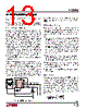
9 / 16 page  9 LTC3404 3404fb Figure 2. Maximum Inductor Peak Current vs Duty Cycle DUTY CYCLE (%) 0 1100 1000 900 800 700 600 80 3404 F02 20 40 60 100 VIN = 3.3V OPERATIO APPLICATIO S I FOR ATIO Slope Compensation and Inductor Peak Current Slope compensation provides stability in constant fre- quency architectures by preventing subharmonic oscilla- tions at high duty cycles. It is accomplished internally by adding a compensating ramp to the inductor current signal at duty cycles in excess of 40%. As a result, the maximum inductor peak current is reduced for duty cycles > 40%. This is shown in the decrease of the inductor peak current as a function of duty cycle graph in Figure 2. The basic LTC3404 application circuit is shown on the first page. External component selection is driven by the load requirement and begins with the selection of L followed by CIN and COUT. Inductor Value Calculation The inductor selection will depend on the operating fre- quency of the LTC3404. The internal nominal frequency is 1.4MHz, but can be externally synchronized from 1MHz to 1.7MHz. The operating frequency and inductor selection are inter- related in that higher operating frequencies allow the use of smaller inductor and capacitor values. However, oper- ating at a higher frequency generally results in lower efficiency because of increased internal gate charge losses. The inductor value has a direct effect on ripple current. The ripple current ΔIL decreases with higher inductance or frequency and increases with higher VIN or VOUT. Δ = ()( ) − ⎛ ⎝⎜ ⎞ ⎠⎟ I fL V V V L OUT OUT IN 1 1 (1) Accepting larger values of ΔIL allows the use of smaller inductors, but results in higher output voltage ripple and greater core losses. A reasonable starting point for setting ripple current is ΔIL = 0.4(IMAX). The inductor value also has an effect on Burst Mode operation. The transition to low current operation begins when the inductor current peaks fall to approximately 250mA. Lower inductor values (higher ΔIL) will cause this to occur at lower load currents, which can cause a dip in efficiency in the upper range of low current operation. In Burst Mode operation, lower inductance values will cause the burst frequency to increase. Inductor Core Selection Once the value for L is known, the type of inductor must be selected. High efficiency converters generally cannot afford the core loss found in low cost powdered iron cores, forcing the use of more expensive ferrite, molypermalloy, or Kool M μ® cores. Actual core loss is independent of core size for a fixed inductor value, but it is very dependent on inductance selected. As inductance increases, core losses go down. Unfortunately, increased inductance requires more turns of wire and therefore copper losses will increase. Ferrite designs have very low core losses and are pre- ferred at high switching frequencies, so design goals can concentrate on copper loss and preventing saturation. Ferrite core material saturates “hard,” which means that inductance collapses abruptly when the peak design cur- rent is exceeded. This results in an abrupt increase in |
|
|
ссылки URL |
| Вашему бизинису помогли Аллдатащит? [ DONATE ] |
Что такое Аллдатащит | реклама | контакт | Конфиденциальность | Ссылка на техническое описание | обмен ссыками | поиск по производителю All Rights Reserved©Alldatasheet.com |
| Russian : Alldatasheetru.com | Korean : Alldatasheet.co.kr | Spanish : Alldatasheet.es | French : Alldatasheet.fr | Italian : Alldatasheetit.com Portuguese : Alldatasheetpt.com | Polish : Alldatasheet.pl | Vietnamese : Alldatasheet.vn Indian : Alldatasheet.in | Mexican : Alldatasheet.com.mx | British : Alldatasheet.co.uk | New Zealand : Alldatasheet.co.nz |
|
Family Site : ic2ic.com |
icmetro.com |
 Russian ▼
 English
 Chinese
 German
 Japanese
 Russian
 Korean
 Spanish
 French
 Italian
 Portuguese
 Polish
 Vietnamese
 Indian
 Mexican
 British
 New Zealand