|
поискавой системы для электроныых деталей |
|
|
поискавой системы для электроныых деталей |
|
ISL6334DIRZ датащи(PDF) 20 Page - Intersil Corporation |
|
|
|||||||||||||||||||||||||||||
ISL6334DIRZ датащи(HTML) 20 Page - Intersil Corporation |
|
|
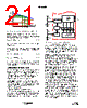
20 / 28 page  20 FN6802.2 August 31, 2010 energy delivered during trip-retry cycling is much less than during full-load operation, so there is no thermal hazard during this kind of operation. For the individual channel overcurrent protection, ISL6334D continuously compares the sensed current signal of each channel with the 129µA reference current. If one channel current exceeds the reference current, ISL6334D will pull PWM signal of this channel to low for the rest of the switching cycle. This PWM signal can be turned on next cycle if the sensed channel current is less than the 129µA reference current. The peak current limit of individual channel will not trigger the converter to shutdown. Thermal Monitoring (VR_HOT/VR_FAN) There are two thermal signals to indicate the temperature status of the voltage regulator: VR_HOT and VR_FAN. Both VR_FAN and VR_HOT pins are open-drain outputs, and external pull-up resistors are required. Those signals are valid only after the controller is enabled. The VR_FAN signal indicates that the temperature of the voltage regulator is high and more cooling airflow is needed. The VR_HOT signal can be used to inform the system that the temperature of the voltage regulator is too high and the CPU should reduce its power consumption. The VR_HOT signal may be tied to the CPU’s PROC_HOT signal. The diagram of thermal monitoring function block is shown in Figure 12. One NTC resistor should be placed close to the power stage of the voltage regulator to sense the operational temperature, and one pull-up resistor is needed to form the voltage divider for the TM pin. As the temperature of the power stage increases, the resistance of the NTC will reduce, resulting in the reduced voltage at the TM pin. Figure 13 shows the TM voltage over the temperature for a typical design with a recommended 6.8k Ω NTC (P/N: NTHS0805N02N6801 from Vishay) and 1k Ω resistor RTM1. We recommend using those resistors for the accurate temperature compensation. There are two comparators with hysteresis to compare the TM pin voltage to the fixed thresholds for VR_FAN and VR_HOT signals respectively. The VR_FAN signal is set to high when the TM voltage is lower than 39.1% of VCC voltage, and is pulled to GND when the TM voltage increases to above 45.1% of VCC voltage. The VR_FAN signal is set to high when the TM voltage goes below 33.3% of VCC voltage, and is pulled to GND when the TM voltage goes back to above 39.1% of VCC voltage. Figure 14 shows the operation of those signals. 0A 0V 2ms/DIV OUTPUT CURRENT FIGURE 11. OVERCURRENT BEHAVIOR IN HICCUP MODE. FSW = 500kHz OUTPUT VOLTAGE FIGURE 12. BLOCK DIAGRAM OF THERMAL MONITORING FUNCTION 0.333VCC 0.391VCC ° C R TM1 R NTC VCC TM VR_FAN VR_HOT FIGURE 13. THE RATIO OF TM VOLTAGE TO NTC TEMPERATURE WITH RECOMMENDED PARTS 20 30 40 50 60 70 80 90 100 0 20 40 60 80 100 120 140 TEMPERATURE (°C) ISL6334D |
|
ссылки URL |
| Вашему бизинису помогли Аллдатащит? [ DONATE ] |
Что такое Аллдатащит | реклама | контакт | Конфиденциальность | Ссылка на техническое описание | обмен ссыками | поиск по производителю All Rights Reserved©Alldatasheet.com |
| Russian : Alldatasheetru.com | Korean : Alldatasheet.co.kr | Spanish : Alldatasheet.es | French : Alldatasheet.fr | Italian : Alldatasheetit.com Portuguese : Alldatasheetpt.com | Polish : Alldatasheet.pl | Vietnamese : Alldatasheet.vn Indian : Alldatasheet.in | Mexican : Alldatasheet.com.mx | British : Alldatasheet.co.uk | New Zealand : Alldatasheet.co.nz |
|
Family Site : ic2ic.com |
icmetro.com |
 Russian ▼
 English
 Chinese
 German
 Japanese
 Russian
 Korean
 Spanish
 French
 Italian
 Portuguese
 Polish
 Vietnamese
 Indian
 Mexican
 British
 New Zealand