|
поискавой системы для электроныых деталей |
|
|
поискавой системы для электроныых деталей |
|
ISL6334DIRZ датащи(PDF) 19 Page - Intersil Corporation |
|
|
|||||||||||||||||||||||||||||
ISL6334DIRZ датащи(HTML) 19 Page - Intersil Corporation |
|
|
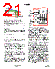
19 / 28 page  19 FN6802.2 August 31, 2010 Fault Monitoring and Protection The ISL6334D actively monitors output voltage and current to detect fault conditions. Fault monitors trigger protective measures to prevent damage to a microprocessor load. One common power-good indicator is provided for linking to external system monitors. The schematic in Figure 10 outlines the interaction between the fault monitors and the VR_RDY signal. VR_RDY Signal The VR_RDY pin is an open-drain logic output which indicates that the soft-start period is complete and the output voltage is within the regulated range. VR_RDY is pulled low during shutdown and releases high after a successful soft- start and a fixed delay tD5. VR_RDY will be pulled low when an undervoltage or overvoltage condition is detected, or the controller is disabled by a reset from EN_PWR, EN_VTT, POR, or VID OFF-code. Undervoltage Detection The undervoltage threshold is set at 50% of the VID code. When the output voltage at VSEN is below the undervoltage threshold, VR_RDY is pulled low. Overvoltage Protection Regardless of the VR being enabled or not, the ISL6334D overvoltage protection (OVP) circuit will be active after its POR. The OVP thresholds are different under different operation conditions. When VR is not enabled and during the soft-start intervals tD1, tD2 and tD3, the OVP threshold is 1.273V. Once the controller detects valid VID input, the OVP trip point will be changed to DAC plus 175mV. Two actions are taken by ISL6334D to protect the microprocessor load when an overvoltage condition occurs. At the inception of an overvoltage event, all PWM outputs are commanded low instantly (less than 20ns). This causes the Intersil drivers to turn on the lower MOSFETs and pull the output voltage below a level to avoid damaging the load. When the VDIFF voltage falls below the DAC plus 75mV, PWM signals enter a high-impedance state. The Intersil drivers respond to the high-impedance input by turning off both upper and lower MOSFETs. If the overvoltage condition reoccurs, ISL6334D will again command the lower MOSFETs to turn on. ISL6334D will continue to protect the load in this fashion as long as the overvoltage condition occurs. Once an overvoltage condition is detected, normal PWM operation ceases until ISL6334D is reset. Cycling the voltage on EN_PWR, EN_VTT or VCC below the POR-falling threshold will reset the controller. Cycling the VID codes will not reset the controller. Overcurrent Protection ISL6334D has two levels of overcurrent protection. Each phase is protected from a sustained overcurrent condition by limiting its peak current, while the combined phase currents are protected on an instantaneous basis. In instantaneous protection mode, ISL6334D utilizes the sensed average current IAVG to detect an overcurrent condition. See “Voltage Regulation” on page 13 for more details on how the average current is measured. The average current is continually compared with a constant 105µA reference current, as shown in Figure 10. Once the average current exceeds the reference current, a comparator triggers the converter to shutdown. The current out of IMON pin is equal to the sensed average current IAVG. With a resistor from IMON to GND, the voltage at IMON will be proportional to the sensed average current and the resistor value. The ISL6334D continuously monitors the voltage at IMON pin. If the voltage at IMON pin is higher than 1.11V, a comparator triggers the overcurrent shutdown. By increasing the resistor between IMON and GND, the overcurrent protection threshold can be adjusted to be less than 105µA. For example, the overcurrent threshold for the sensed average current IAVG can be set to 95µA by using a 11.8k Ω resistor from IMON to GND. At the beginning of overcurrent shutdown, the controller places all PWM signals in a high-impedance state within 20ns, commanding the Intersil MOSFET driver ICs to turn off both upper and lower MOSFETs. The system remains in this state a period of 4096 switching cycles. If the controller is still enabled at the end of this wait period, it will attempt a soft-start. If the fault remains, the trip-retry cycles will continue indefinitely (as shown in Figure 11) until either controller is disabled or the fault is cleared. Note that the FIGURE 10. VR_RDY AND PROTECTION CIRCUITRY - + VID + 0.175V VDIFF - + 105µA IAVG DAC OV OC UV VR_RDY 50% SOFT-START, FAULT AND CONTROL LOGIC - + OC IMON 1.11V ISL6334D |
|
ссылки URL |
| Вашему бизинису помогли Аллдатащит? [ DONATE ] |
Что такое Аллдатащит | реклама | контакт | Конфиденциальность | Ссылка на техническое описание | обмен ссыками | поиск по производителю All Rights Reserved©Alldatasheet.com |
| Russian : Alldatasheetru.com | Korean : Alldatasheet.co.kr | Spanish : Alldatasheet.es | French : Alldatasheet.fr | Italian : Alldatasheetit.com Portuguese : Alldatasheetpt.com | Polish : Alldatasheet.pl | Vietnamese : Alldatasheet.vn Indian : Alldatasheet.in | Mexican : Alldatasheet.com.mx | British : Alldatasheet.co.uk | New Zealand : Alldatasheet.co.nz |
|
Family Site : ic2ic.com |
icmetro.com |
 Russian ▼
 English
 Chinese
 German
 Japanese
 Russian
 Korean
 Spanish
 French
 Italian
 Portuguese
 Polish
 Vietnamese
 Indian
 Mexican
 British
 New Zealand