|
поискавой системы для электроныых деталей |
|
|
поискавой системы для электроныых деталей |
|
TC820CPL датащи(PDF) 11 Page - TelCom Semiconductor, Inc |
|
|
|||||||||||||||||||||||||||||
TC820CPL датащи(HTML) 11 Page - TelCom Semiconductor, Inc |
|
|
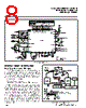
11 / 22 page  3-159 TELCOM SEMICONDUCTOR, INC. 7 6 5 4 3 1 2 8 If the logic probe is active while FREQ/VOLTS is high (counter mode), the frequency counter will continue to operate. The display will read "OL" but the decimal points will be visible. If the logic probe input is also connected to the RANGE/FREQ input, bringing the LOGIC input low will immediately display the frequency at the logic probe input. Analog Pin Functional Description Differential Signal Inputs (V + IN), (V – IN) The TC820 is designed with true differential inputs, and accepts input signals within the input stage common-mode voltage (VCM) range. The typical range is VDD –1V to VSS +1.5V. Common-mode voltages are removed from the sys- tem when the TC820 operates from a battery or floating power source (isolated from measured system) and VSS is connected to analog common. (See Figure 8.) TC820 3-3/4 A/D CONVERTER WITH FREQUENCY COUNTER AND LOGIC PROBE Thus, the counter will operate with a 1-second time base when a 40 kHz oscillator is used. The frequency counter accuracy is determined by the oscillator accuracy. For accurate frequency measurements, a crystal oscillator is recommended. The frequency counter will automatically select the proper range. Auto-range operation extends over four decades, from 3.999 kHz to 3.999 MHz. Decimal points are set automatically in the frequency mode (Figure 5). The logic switching levels of the RANGE/FREQ input are CMOS levels. For best counter operation, an external buffer is recommended. See the applications section for details. Logic Probe The TC820 can also function as a simple logic probe (Figure 6). This mode is selected when the LOGIC input is high. Two dual-purpose pins, which normally control the decimal points, are used as logic inputs. Connecting either input to a logic high level will turn on the corresponding LCD annunciator. When the "low" annunciator is on the buzzer will be on. As with the frequency counter input, external level shifters/buffers are recommended for the logic probe inputs. When the logic probe function is selected while FREQ/ VOLTS is low (A/D mode), the ADC will remain in the auto- zero mode. The LCD will read "OL" and all decimal points will be off (Figure 7). DATA LATCH, PEAK HOLD REGISTER, LCD DECODER/DRIVERS OVERRANGE DETECT UNDERRANGE DETECT AUTO-RANGE CONTROL PROGRAMMABLE DIVIDER ( ÷1, 10, 100, 1000) CLOCK OSCILLATOR TO DECIMAL POINT DRIVERS FREQUENCY INPUT RANGE/ FREQ ÷20,000 FROM INTEGRATOR OF A/D CONVERTER COMPARATOR LCD 3-3/4 DIGIT COUNTER ENABLE COUNT OVERFLOW A/D CONVERTER FREQUENCY COUNTER A/D CONVERTER/FREQUENCY COUNTER SELECT TC820 ÷2 FREQ/ VOLTS Figure 4. TC820 Counter Operation |
|
|
ссылки URL |
| Вашему бизинису помогли Аллдатащит? [ DONATE ] |
Что такое Аллдатащит | реклама | контакт | Конфиденциальность | Ссылка на техническое описание | обмен ссыками | поиск по производителю All Rights Reserved©Alldatasheet.com |
| Russian : Alldatasheetru.com | Korean : Alldatasheet.co.kr | Spanish : Alldatasheet.es | French : Alldatasheet.fr | Italian : Alldatasheetit.com Portuguese : Alldatasheetpt.com | Polish : Alldatasheet.pl | Vietnamese : Alldatasheet.vn Indian : Alldatasheet.in | Mexican : Alldatasheet.com.mx | British : Alldatasheet.co.uk | New Zealand : Alldatasheet.co.nz |
|
Family Site : ic2ic.com |
icmetro.com |
 Russian ▼
 English
 Chinese
 German
 Japanese
 Russian
 Korean
 Spanish
 French
 Italian
 Portuguese
 Polish
 Vietnamese
 Indian
 Mexican
 British
 New Zealand