|
поискавой системы для электроныых деталей |
|
|
поискавой системы для электроныых деталей |
|
PIC16F631 датащи(PDF) 187 Page - Microchip Technology |
|
|
|||||||||||||||||||||||||||||
PIC16F631 датащи(HTML) 187 Page - Microchip Technology |
|
|
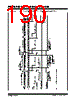
187 / 294 page  © 2007 Microchip Technology Inc. DS41262D-page 185 PIC16F631/677/685/687/689/690 13.12.1 ADDRESSING Once the SSP module has been enabled, it waits for a Start condition to occur. Following the Start condition, the 8-bits are shifted into the SSPSR register. All incoming bits are sampled with the rising edge of the clock (SCL) line. The value of register SSPSR<7:1> is compared to the value of the SSPADD register. The address is compared on the falling edge of the eighth clock (SCL) pulse. If the addresses match, and the BF and SSPOV bits are clear, the following events occur: a) The SSPSR register value is loaded into the SSPBUF register. b) The buffer full bit, BF is set. c) An ACK pulse is generated. d) SSP interrupt flag bit, SSPIF of the PIR1 register is set (interrupt is generated if enabled) on the falling edge of the ninth SCL pulse. In 10-bit Address mode, two address bytes need to be received by the slave (Figure 13-8). The five Most Significant bits (MSbs) of the first address byte specify if this is a 10-bit address. Bit R/W (SSPSTAT<2>) must specify a write so the slave device will receive the second address byte. For a 10-bit address, the first byte would equal ‘1111 0 A9 A8 0’, where A9 and A8 are the two MSbs of the address. The sequence of events for 10-bit address is as follows, with steps 7-9 for slave-transmitter: 1. Receive first (high) byte of address (bits SSPIF, BF and bit UA (SSPSTAT<1>) are set). 2. Update the SSPADD register with second (low) byte of address (clears bit UA and releases the SCL line). 3. Read the SSPBUF register (clears bit BF) and clear flag bit SSPIF. 4. Receive second (low) byte of address (bits SSPIF, BF and UA are set). 5. Update the SSPADD register with the first (high) byte of address; if match releases SCL line, this will clear bit UA. 6. Read the SSPBUF register (clears bit BF) and clear flag bit SSPIF. 7. Receive repeated Start condition. 8. Receive first (high) byte of address (bits SSPIF and BF are set). 9. Read the SSPBUF register (clears bit BF) and clear flag bit SSPIF. TABLE 13-3: DATA TRANSFER RECEIVED BYTE ACTIONS Status Bits as Data Transfer is Received SSPSR → SSPBUF Generate ACK Pulse Set bit SSPIF (SSP Interrupt occurs if enabled) BF SSPOV 00 Yes Yes Yes 10 No No Yes 11 No No Yes 0 1 No No Yes Note: Shaded cells show the conditions where the user software did not properly clear the overflow condition. |
|
ссылки URL |
| Вашему бизинису помогли Аллдатащит? [ DONATE ] |
Что такое Аллдатащит | реклама | контакт | Конфиденциальность | Ссылка на техническое описание | обмен ссыками | поиск по производителю All Rights Reserved©Alldatasheet.com |
| Russian : Alldatasheetru.com | Korean : Alldatasheet.co.kr | Spanish : Alldatasheet.es | French : Alldatasheet.fr | Italian : Alldatasheetit.com Portuguese : Alldatasheetpt.com | Polish : Alldatasheet.pl | Vietnamese : Alldatasheet.vn Indian : Alldatasheet.in | Mexican : Alldatasheet.com.mx | British : Alldatasheet.co.uk | New Zealand : Alldatasheet.co.nz |
|
Family Site : ic2ic.com |
icmetro.com |
 Russian ▼
 English
 Chinese
 German
 Japanese
 Russian
 Korean
 Spanish
 French
 Italian
 Portuguese
 Polish
 Vietnamese
 Indian
 Mexican
 British
 New Zealand