|
поискавой системы для электроныых деталей |
|
|
поискавой системы для электроныых деталей |
|
PIC16F631 датащи(PDF) 141 Page - Microchip Technology |
|
|
|||||||||||||||||||||||||||||
PIC16F631 датащи(HTML) 141 Page - Microchip Technology |
|
|
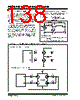
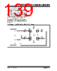
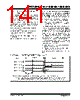
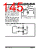
141 / 294 page  © 2007 Microchip Technology Inc. DS41262D-page 139 PIC16F631/677/685/687/689/690 11.4.2.1 Direction Change in Full-Bridge Mode In the Full-Bridge mode, the P1M1 bit in the CCP1CON register allows users to control the forward/reverse direction. When the application firmware changes this direction control bit, the module will change to the new direction on the next PWM cycle. A direction change is initiated in software by changing the P1M1 bit of the CCP1CON register. The following sequence occurs four Timer2 cycles prior to the end of the current PWM period: • The modulated outputs (P1B and P1D) are placed in their inactive state. • The associated unmodulated outputs (P1A and P1C) are switched to drive in the opposite direction. • PWM modulation resumes at the beginning of the next period. See Figure 11-12 for an illustration of this sequence. The Full-Bridge mode does not provide dead-band delay. As one output is modulated at a time, dead-band delay is generally not required. There is a situation where dead-band delay is required. This situation occurs when both of the following conditions are true: 1. The direction of the PWM output changes when the duty cycle of the output is at or near 100%. 2. The turn off time of the power switch, including the power device and driver circuit, is greater than the turn on time. Figure 11-13 shows an example of the PWM direction changing from forward to reverse, at a near 100% duty cycle. In this example, at time t1, the output P1A and P1D become inactive, while output P1C becomes active. Since the turn off time of the power devices is longer than the turn on time, a shoot-through current will flow through power devices QC and QD (see Figure 11-10) for the duration of ‘t’. The same phenomenon will occur to power devices QA and QB for PWM direction change from reverse to forward. If changing PWM direction at high duty cycle is required for an application, two possible solutions for eliminating the shoot-through current are: 1. Reduce PWM duty cycle for one PWM period before changing directions. 2. Use switch drivers that can drive the switches off faster than they can drive them on. Other options to prevent shoot-through current may exist. FIGURE 11-12: EXAMPLE OF PWM DIRECTION CHANGE Pulse Width Period(1) Signal Note 1: The direction bit P1M1 of the CCP1CON register is written any time during the PWM cycle. 2: When changing directions, the P1A and P1C signals switch before the end of the current PWM cycle. The modulated P1B and P1D signals are inactive at this time. The length of this time is four Timer2 counts. Period (2) P1A (Active-High) P1B (Active-High) P1C (Active-High) P1D (Active-High) Pulse Width |
|
ссылки URL |
| Вашему бизинису помогли Аллдатащит? [ DONATE ] |
Что такое Аллдатащит | реклама | контакт | Конфиденциальность | Ссылка на техническое описание | обмен ссыками | поиск по производителю All Rights Reserved©Alldatasheet.com |
| Russian : Alldatasheetru.com | Korean : Alldatasheet.co.kr | Spanish : Alldatasheet.es | French : Alldatasheet.fr | Italian : Alldatasheetit.com Portuguese : Alldatasheetpt.com | Polish : Alldatasheet.pl | Vietnamese : Alldatasheet.vn Indian : Alldatasheet.in | Mexican : Alldatasheet.com.mx | British : Alldatasheet.co.uk | New Zealand : Alldatasheet.co.nz |
|
Family Site : ic2ic.com |
icmetro.com |
 Russian ▼
 English
 Chinese
 German
 Japanese
 Russian
 Korean
 Spanish
 French
 Italian
 Portuguese
 Polish
 Vietnamese
 Indian
 Mexican
 British
 New Zealand