|
поискавой системы для электроныых деталей |
|
|
поискавой системы для электроныых деталей |
|
PIC16F631 датащи(PDF) 143 Page - Microchip Technology |
|
|
|||||||||||||||||||||||||||||
PIC16F631 датащи(HTML) 143 Page - Microchip Technology |
|
|
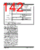
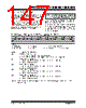
143 / 294 page  © 2007 Microchip Technology Inc. DS41262D-page 141 PIC16F631/677/685/687/689/690 11.4.4 ENHANCED PWM AUTO-SHUTDOWN MODE The PWM mode supports an Auto-Shutdown mode that will disable the PWM outputs when an external shutdown event occurs. Auto-Shutdown mode places the PWM output pins into a predetermined state. This mode is used to help prevent the PWM from damaging the application. The auto-shutdown sources are selected using the ECCPASx bits of the ECCPAS register. A shutdown event may be generated by: •A logic ‘0’ on the INT pin • Comparator C1 • Comparator C2 • Setting the ECCPASE bit in firmware A shutdown condition is indicated by the ECCPASE (Auto-Shutdown Event Status) bit of the ECCPAS register. If the bit is a ‘0’, the PWM pins are operating normally. If the bit is a ‘1’, the PWM outputs are in the shutdown state. When a shutdown event occurs, two things happen: The ECCPASE bit is set to ‘1’. The ECCPASE will remain set until cleared in firmware or an auto-restart occurs (see Section 11.4.5 “Auto-Restart Mode”). The enabled PWM pins are asynchronously placed in their shutdown states. The PWM output pins are grouped into pairs [P1A/P1C] and [P1B/P1D]. The state of each pin pair is determined by the PSSAC and PSSBD bits of the ECCPAS register. Each pin pair may be placed into one of three states: • Drive logic ‘1’ • Drive logic ‘0’ • Tri-state (high-impedance) REGISTER 11-2: ECCPAS: ENHANCED CAPTURE/COMPARE/PWM AUTO-SHUTDOWN CONTROL REGISTER U-0 U-0 R/W-0 R/W-0 R/W-0 R/W-0 R/W-0 R/W-0 ECCPASE ECCPAS2 ECCPAS1 ECCPAS0 PSSAC1 PSSAC0 PSSBD1 PSSBD0 bit 7 bit 0 Legend: R = Readable bit W = Writable bit U = Unimplemented bit, read as ‘0’ -n = Value at POR ‘1’ = Bit is set ‘0’ = Bit is cleared x = Bit is unknown bit 7 ECCPASE: ECCP Auto-Shutdown Event Status bit 1 = A shutdown event has occurred; ECCP outputs are in shutdown state 0 = ECCP outputs are operating bit 6-4 ECCPAS<2:0>: ECCP Auto-shutdown Source Select bits 000 = Auto-Shutdown is disabled 001 = Comparator C1 output change 010 = Comparator C2 output change(1) 011 = Either Comparator C1 or C2 change 100 =VIL on INT pin 101 =VIL on INT pin or Comparator C1 change 110 =VIL on INT pin or Comparator C2 change 111 =VIL on INT pin or Comparator C1 or C2 change bit 3-2 PSSACn: Pins P1A and P1C Shutdown State Control bits 00 = Drive pins P1A and P1C to ‘0’ 01 = Drive pins P1A and P1C to ‘1’ 1x = Pins P1A and P1C tri-state bit 1-0 PSSBDn: Pins P1B and P1D Shutdown State Control bits 00 = Drive pins P1B and P1D to ‘0’ 01 = Drive pins P1B and P1D to ‘1’ 1x = Pins P1B and P1D tri-state Note 1: If C2SYNC is enabled, the shutdown will be delayed by Timer1. |
|
ссылки URL |
| Вашему бизинису помогли Аллдатащит? [ DONATE ] |
Что такое Аллдатащит | реклама | контакт | Конфиденциальность | Ссылка на техническое описание | обмен ссыками | поиск по производителю All Rights Reserved©Alldatasheet.com |
| Russian : Alldatasheetru.com | Korean : Alldatasheet.co.kr | Spanish : Alldatasheet.es | French : Alldatasheet.fr | Italian : Alldatasheetit.com Portuguese : Alldatasheetpt.com | Polish : Alldatasheet.pl | Vietnamese : Alldatasheet.vn Indian : Alldatasheet.in | Mexican : Alldatasheet.com.mx | British : Alldatasheet.co.uk | New Zealand : Alldatasheet.co.nz |
|
Family Site : ic2ic.com |
icmetro.com |
 Russian ▼
 English
 Chinese
 German
 Japanese
 Russian
 Korean
 Spanish
 French
 Italian
 Portuguese
 Polish
 Vietnamese
 Indian
 Mexican
 British
 New Zealand