|
поискавой системы для электроныых деталей |
|
|
поискавой системы для электроныых деталей |
|
LT1794 датащи(PDF) 12 Page - Linear Technology |
|
|
|||||||||||||||||||||||||||||
LT1794 датащи(HTML) 12 Page - Linear Technology |
|
|
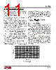
12 / 20 page  12 LT1794 EXAMPLE A θJA = 40°C/W 13MIL VIAS USED: 30 EXAMPLE B θJA = 47°C/W 13MIL VIAS USED: 35 EXAMPLE C θJA = 51°C/W 13MIL VIAS USED: 32 EXAMPLE D θJA = 60°C/W 13MIL VIAS USED: 22 TOPOLOGY TOP LAYER 2nd LAYER 3rd LAYER BOTTOM LAYER VIA PATTERN 1794 F08 SCALE: 1 INCH APPLICATIO S I FOR ATIO Figure 8. Examples of PCB Metal Used for Heat Dissipation. LT1794IFE Driver Mounted on Top Layer. Heat Sink Pad Soldered to Top Layer Metal. External Components Mounted on Bottom Layer Figure 8 shows four examples of PCB metal being used for heat spreading. These are provided as a reference for what might be expected when using different combinations of metal area on different layers of a PCB. These examples are with a 4-layer board using 1oz copper on each. The most effective layers for spreading heat are those closest to the LT1794 junction. The LT1794IFE is used because the small TSSOP package is most effective for very compact line driver designs. This package also has an exposed metal heat sinking pad on the bottom side which, when soldered to the PCB top layer metal, directly conducts heat away from the IC junction. Soldering the thermal pad to the board produces a thermal resistance from junction to case, θJC, of approximately 3°C/W. Example A utilizes the most total metal area and provides the lowest thermal resistance. Example B however uses less metal on the top and bottom layers and still achieves reasonable thermal performance. For the most compact board design, inner layer metal can be used for heat dissipation. This is shown in examples C and D where minimum metal is used on the top and none on the bottom layers, only the 2nd and 3rd layers have a heat-conducting plane. Example C, with the larger metal areas performs better. |
|
|
ссылки URL |
| Вашему бизинису помогли Аллдатащит? [ DONATE ] |
Что такое Аллдатащит | реклама | контакт | Конфиденциальность | Ссылка на техническое описание | обмен ссыками | поиск по производителю All Rights Reserved©Alldatasheet.com |
| Russian : Alldatasheetru.com | Korean : Alldatasheet.co.kr | Spanish : Alldatasheet.es | French : Alldatasheet.fr | Italian : Alldatasheetit.com Portuguese : Alldatasheetpt.com | Polish : Alldatasheet.pl | Vietnamese : Alldatasheet.vn Indian : Alldatasheet.in | Mexican : Alldatasheet.com.mx | British : Alldatasheet.co.uk | New Zealand : Alldatasheet.co.nz |
|
Family Site : ic2ic.com |
icmetro.com |
 Russian ▼
 English
 Chinese
 German
 Japanese
 Russian
 Korean
 Spanish
 French
 Italian
 Portuguese
 Polish
 Vietnamese
 Indian
 Mexican
 British
 New Zealand