|
поискавой системы для электроныых деталей |
|
|
поискавой системы для электроныых деталей |
|
HCS473 датащи(PDF) 32 Page - Microchip Technology |
|
|
|||||||||||||||||||||||||||||
HCS473 датащи(HTML) 32 Page - Microchip Technology |
|
|
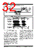
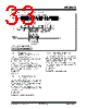
32 / 68 page  HCS473 DS40035D-page 32 Preliminary 2000-2013 Microchip Technology Inc. FIGURE 3-20: LF DATA RESPONSE ADJUSTMENTS (LFRSP=1) FIGURE 3-21: LF COMMUNICATION ANALOG DELAYS 3.2.7 RECEIVE STABILITY - CALCULATING COMMUNICATION TE The HCS473’s internal oscillator may vary ±10% over the device’s rated voltage and temperature range for commercial temperature devices. A certain percentage of industrial temperature devices vary further on the slow side, -20%, when used at higher voltages (VDD > 3.5V) and cold temperature. When the internal oscilla- tor varies, both its transmitted TE and expected TE when receiving will vary. The HCS473 receive capability is ensured over a ±10% oscillator variance, with receive capability no longer robust as oscillator variance approaches ±15%. Indus- trial devices operating at VDD voltages greater than 3.5V (and cold temperature) are therefore not guaran- teed to be able to properly receive when communicated to using an exact TE. When designing for these specific operating conditions, the system designer must imple- ment a method to adjust communication timing to the speed of the HCS473. Communication reliability with the transponder may be improved by the transponder reader calculating the HCS473’s TE from the Field Acknowledge sequence and using this exact time element in communication to and in reception routines from the transponder. Always begin and end the time measurement on rising edges. Whether LF or RF, the falling edge decay rates may vary but the rising edge relationships should remain consistent. A common TE calculation method would be to time an 8TE sequence from the first Field Acknowledge, then divide the value down to determine the single TE value. An 8 TE measurement will give good resolution and may be easily right-shifted (divide by 2) three times for the math portion of the calculation (Figure 3-22). IFF, Read and Request Hop CRC RF Response (RFRSP=1) Inductive (LC Pins) RF Response (DATA Pin) 32-Bit LF Response (LFRSP=1) TFINH 1 LFTE Next Command TCMD TCMD Resulting 125 kHz on Transponder Reader Digital Representation of Communication from Transponder Reader Antenna (TX) 600 s 400 s Resulting 125 kHz on Transponder Card Antenna (RX) Resulting digital signal processed by HCS473, after analog filter 600 s 400 s TFILTR TFILTF TANTR TANTF Bit ‘1’, 200 s LFTE Bit ‘0’, 200 s LFTE |
|
ссылки URL |
| Вашему бизинису помогли Аллдатащит? [ DONATE ] |
Что такое Аллдатащит | реклама | контакт | Конфиденциальность | Ссылка на техническое описание | обмен ссыками | поиск по производителю All Rights Reserved©Alldatasheet.com |
| Russian : Alldatasheetru.com | Korean : Alldatasheet.co.kr | Spanish : Alldatasheet.es | French : Alldatasheet.fr | Italian : Alldatasheetit.com Portuguese : Alldatasheetpt.com | Polish : Alldatasheet.pl | Vietnamese : Alldatasheet.vn Indian : Alldatasheet.in | Mexican : Alldatasheet.com.mx | British : Alldatasheet.co.uk | New Zealand : Alldatasheet.co.nz |
|
Family Site : ic2ic.com |
icmetro.com |
 Russian ▼
 English
 Chinese
 German
 Japanese
 Russian
 Korean
 Spanish
 French
 Italian
 Portuguese
 Polish
 Vietnamese
 Indian
 Mexican
 British
 New Zealand