|
поискавой системы для электроныых деталей |
|
|
поискавой системы для электроныых деталей |
|
UCC28070 датащи(PDF) 4 Page - Texas Instruments |
|
|
|
|||||||||||||||||||||||||||||
UCC28070 датащи(HTML) 4 Page - Texas Instruments |
|
|
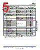
4 / 27 page  www.ti.com UCC28070 SLUS794 – NOVEMBER 2007 ELECTRICAL CHARACTERISTICS (continued) over operating free-air temperature range −40 °C < T A < 125°C, TJ = TA, VCC = 12 V, GND = 0 V, RRT = 75 kΩ, RDMX = 67.5 k Ω, RRDM = RSYN = 100 kΩ, RIMO = 16 kΩ, CCDR = 625 pF, CSS = CVREF = 0.1 µF, CVCC = 1 µF, (unless otherwise noted) SYMBOL PARAMETER TEST CONDITIONS MIN TYP MAX UNITS Clock Synchronization VCDR SYNC enable threshold Measured at CDR (rising) 5 TBD V VCDR = 6 V, Measured from RDM (rising) to SYNC propagation delay 50 TBD ns GDx (rising) SYNC threshold (Rising) VCDR = 6 V, Measured at RDM (rising) 1.2 1.5 V SYNC threshold (Falling) VCDR = 6 V, Measured at RDM (falling) 0.4 0.7 Positive pulse width 0.2 µs SYNC pulses Maximum duty cycle (2) 75 % Voltage Amplifier VSENSE voltage In regulation, TA = 25°C 2.97 3 3.03 V VSENSE voltage In regulation 2.94 3 3.06 VSENSE input bias current In regulation 250 TBD nA VAO high voltage VSENSE = 2.9 V 4.8 5 5.2 V VAO low voltage VSENSE = 3.1 V 0.05 TBD gMV VAO transconductance 2.8 V < VSENSE < 3.2 V, VAO = 3 V 70 µS VAO sink current, overdriven limit VSENSE = 3.5 V, VAO = 3 V 30 VAO source current, overdriven VSENSE = 2.5 V, VAO = 3 V, SS = 3 V −30 µA VAO source current, VSENSE = 2.5 V, VAO = 3 V −130 overdriven limit + ISRC Measured as VSENSE (falling) / VSENSE Slew-rate correction threshold 92 93 95 % (regulation) Slew-rate correction hysteresis Measured at VSENSE (rising) 6 TBD mV Measured at VAO, in addition to VAO ISRC Slew-rate correction current −100 µA source current. Slew-rate correction enable threshold Measured at SS (rising) 4 V VAO discharge current VSENSE = 0.5 V, VAO = 1 V 10 µA Soft Start ISS SS source current VSENSE = 0.9 V, SS = 1 V −10 µA Adaptive source current VSENSE = 1.1 V, SS = 1 V −1 mA Adaptive SS disable Measured as VSENSE – SS 0 mV SS sink current VSENSE = 0.5 V, SS = 0.2 V 0.5 0.9 mA (2) Due to the programmability of the maximum PWM switching duty cycle (DMAX), the maximum duty cycle of a synchronization pulse must be reasonably (~5-10%) less than 2 x DMAX -1. 4 Submit Documentation Feedback Copyright © 2007, Texas Instruments Incorporated Product Folder Link(s): UCC28070 |
|
|
ссылки URL |
| Вашему бизинису помогли Аллдатащит? [ DONATE ] |
Что такое Аллдатащит | реклама | контакт | Конфиденциальность | Ссылка на техническое описание | обмен ссыками | поиск по производителю All Rights Reserved©Alldatasheet.com |
| Russian : Alldatasheetru.com | Korean : Alldatasheet.co.kr | Spanish : Alldatasheet.es | French : Alldatasheet.fr | Italian : Alldatasheetit.com Portuguese : Alldatasheetpt.com | Polish : Alldatasheet.pl | Vietnamese : Alldatasheet.vn Indian : Alldatasheet.in | Mexican : Alldatasheet.com.mx | British : Alldatasheet.co.uk | New Zealand : Alldatasheet.co.nz |
|
Family Site : ic2ic.com |
icmetro.com |
 Russian ▼
 English
 Chinese
 German
 Japanese
 Russian
 Korean
 Spanish
 French
 Italian
 Portuguese
 Polish
 Vietnamese
 Indian
 Mexican
 British
 New Zealand