|
поискавой системы для электроныых деталей |
|
|
поискавой системы для электроныых деталей |
|
PIC16F631 датащи(PDF) 201 Page - Microchip Technology |
|
|
|||||||||||||||||||||||||||||
PIC16F631 датащи(HTML) 201 Page - Microchip Technology |
|
|
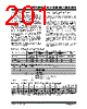
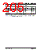
201 / 294 page  © 2007 Microchip Technology Inc. DS41262D-page 199 PIC16F631/677/685/687/689/690 14.2.5 TIME-OUT SEQUENCE On power-up, the time-out sequence is as follows: first, PWRT time-out is invoked after POR has expired, then OST is activated after the PWRT time-out has expired. The total time-out will vary based on oscillator configuration and PWRTE bit status. For example, in EC mode with PWRTE bit erased (PWRT disabled), there will be no time-out at all. Figures 14-4, 14-5 and 14-6 depict time-out sequences. The device can execute code from the INTOSC while OST is active by enabling Two-Speed Start-up or Fail-Safe Monitor (see Section 3.7.2 “Two-speed Start-up Sequence” and Section 3.8 “Fail-Safe Clock Monitor”). Since the time-outs occur from the POR pulse, if MCLR is kept low long enough, the time-outs will expire. Then, bringing MCLR high will begin execution immediately (see Figure 14-5). This is useful for testing purposes or to synchronize more than one PIC16F631/677/685/ 687/689/690 device operating in parallel. Table 14-5 shows the Reset conditions for some special registers, while Table 14-4 shows the Reset conditions for all the registers. 14.2.6 POWER CONTROL (PCON) REGISTER The Power Control register PCON (address 8Eh) has two Status bits to indicate what type of Reset that last occurred. Bit 0 is BOR (Brown-out Reset). BOR is unknown on Power-on Reset. It must then be set by the user and checked on subsequent Resets to see if BOR = 0, indicating that a Brown-out has occurred. The BOR Status bit is a “don’t care” and is not necessarily predictable if the brown-out circuit is disabled (BOREN<1:0> = 00 in the Configuration Word register). Bit 1 is POR (Power-on Reset). It is a ‘0’ on Power-on Reset and unaffected otherwise. The user must write a ‘1’ to this bit following a Power-on Reset. On a subsequent Reset, if POR is ‘0’, it will indicate that a Power-on Reset has occurred (i.e., VDD may have gone too low). For more information, see Section 4.2.4 “Ultra Low- Power Wake-up” and Section 14.2.4 “Brown-out Reset (BOR)”. TABLE 14-1: TIME-OUT IN VARIOUS SITUATIONS TABLE 14-2: STATUS/PCON BITS AND THEIR SIGNIFICANCE TABLE 14-3: SUMMARY OF REGISTERS ASSOCIATED WITH BROWN-OUT Oscillator Configuration Power-up Brown-out Reset Wake-up from Sleep PWRTE = 0 PWRTE = 1 PWRTE = 0 PWRTE = 1 XT, HS, LP TPWRT + 1024 • TOSC 1024 • TOSC TPWRT + 1024 • TOSC 1024 • TOSC 1024 • TOSC LP, T1OSCIN = 1 TPWRT —TPWRT —— RC, EC, INTOSC TPWRT —TPWRT —— POR BOR TO PD Condition 0x11 Power-on Reset u011 Brown-out Reset uu0u WDT Reset uu00 WDT Wake-up uuuu MCLR Reset during normal operation uu10 MCLR Reset during Sleep Legend: u = unchanged, x = unknown Name Bit 7 Bit 6 Bit 5 Bit 4 Bit 3 Bit 2 Bit 1 Bit 0 Value on POR, BOR Value on all other Resets PCON — — ULPWUE SBOREN — —POR BOR --01 --qq --0u --uu STATUS IRP RP1 RPO TO PD Z DC C 0001 1xxx 000q quuu Legend: u = unchanged, x = unknown, – = unimplemented bit, reads as ‘0’, q = value depends on condition. Shaded cells are not used by BOR. Note 1: Other (non Power-up) Resets include MCLR Reset and Watchdog Timer Reset during normal operation. |
|
ссылки URL |
| Вашему бизинису помогли Аллдатащит? [ DONATE ] |
Что такое Аллдатащит | реклама | контакт | Конфиденциальность | Ссылка на техническое описание | обмен ссыками | поиск по производителю All Rights Reserved©Alldatasheet.com |
| Russian : Alldatasheetru.com | Korean : Alldatasheet.co.kr | Spanish : Alldatasheet.es | French : Alldatasheet.fr | Italian : Alldatasheetit.com Portuguese : Alldatasheetpt.com | Polish : Alldatasheet.pl | Vietnamese : Alldatasheet.vn Indian : Alldatasheet.in | Mexican : Alldatasheet.com.mx | British : Alldatasheet.co.uk | New Zealand : Alldatasheet.co.nz |
|
Family Site : ic2ic.com |
icmetro.com |
 Russian ▼
 English
 Chinese
 German
 Japanese
 Russian
 Korean
 Spanish
 French
 Italian
 Portuguese
 Polish
 Vietnamese
 Indian
 Mexican
 British
 New Zealand