|
поискавой системы для электроныых деталей |
|
|
поискавой системы для электроныых деталей |
|
PIC16F631 датащи(PDF) 197 Page - Microchip Technology |
|
|
|||||||||||||||||||||||||||||
PIC16F631 датащи(HTML) 197 Page - Microchip Technology |
|
|
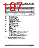
197 / 294 page  © 2007 Microchip Technology Inc. DS41262D-page 195 PIC16F631/677/685/687/689/690 REGISTER 14-1: CONFIG: CONFIGURATION WORD REGISTER Reserved Reserved FCMEN IESO BOREN1(1) BOREN0(1) CPD(2 bit 13 bit 7 CP(3) MCLRE(4) PWRTE WDTE FOSC2 FOSC1 FOSC0 bit 6 bit 0 Legend: R = Readable bit W = Writable bit P = Programmable’ U = Unimplemented bit, read as ‘0’ -n = Value at POR ‘1’ = Bit is set ‘0’ = Bit is cleared x = Bit is unknown bit 13-12 Reserved: Reserved bits. Do Not Use. bit 11 FCMEN: Fail-Safe Clock Monitor Enabled bit 1 = Fail-Safe Clock Monitor is enabled 0 = Fail-Safe Clock Monitor is disabled bit 10 IESO: Internal External Switchover bit 1 = Internal External Switchover mode is enabled 0 = Internal External Switchover mode is disabled bit 9-8 BOREN<1:0>: Brown-out Reset Selection bits(1) 11 = BOR enabled 10 = BOR enabled during operation and disabled in Sleep 01 = BOR controlled by SBOREN bit of the PCON register 00 = BOR disabled bit 7 CPD: Data Code Protection bit(2) 1 = Data memory code protection is disabled 0 = Data memory code protection is enabled bit 6 CP: Code Protection bit(2) 1 = Program memory code protection is disabled 0 = Program memory code protection is enabled bit 5 MCLRE: MCLR Pin Function Select bit(3) 1 = MCLR pin function is MCLR 0 = MCLR pin function is digital input, MCLR internally tied to VDD bit 4 PWRTE: Power-up Timer Enable bit 1 = PWRT disabled 0 = PWRT enabled bit 3 WDTE: Watchdog Timer Enable bit 1 = WDT enabled 0 = WDT disabled bit 2-0 FOSC<2:0>: Oscillator Selection bits 111 = RC oscillator: CLKOUT function on RA4/OSC2/CLKOUT pin, RC on RA5/OSC1/CLKIN 110 = RCIO oscillator: I/O function on RA4/OSC2/CLKOUT pin, RC on RA5/OSC1/CLKIN 101 = INTOSC oscillator: CLKOUT function on RA4/OSC2/CLKOUT pin, I/O function on RA5/OSC1/CLKIN 100 = INTOSCIO oscillator: I/O function on RA4/OSC2/CLKOUT pin, I/O function on RA5/OSC1/CLKIN 011 = EC: I/O function on RA4/OSC2/CLKOUT pin, CLKIN on RA5/OSC1/CLKIN 010 = HS oscillator: High-speed crystal/resonator on RA4/OSC2/CLKOUT and RA5/OSC1/CLKIN 001 = XT oscillator: Crystal/resonator on RA4/OSC2/CLKOUT and RA5/OSC1/CLKIN 000 = LP oscillator: Low-power crystal on RA4/OSC2/CLKOUT and RA5/OSC1/CLKIN Note 1: Enabling Brown-out Reset does not automatically enable Power-up Timer. 2: The entire data EEPROM will be erased when the code protection is turned off. 3: The entire program memory will be erased when the code protection is turned off. 4: When MCLR is asserted in INTOSC or RC mode, the internal clock oscillator is disabled. |
|
ссылки URL |
| Вашему бизинису помогли Аллдатащит? [ DONATE ] |
Что такое Аллдатащит | реклама | контакт | Конфиденциальность | Ссылка на техническое описание | обмен ссыками | поиск по производителю All Rights Reserved©Alldatasheet.com |
| Russian : Alldatasheetru.com | Korean : Alldatasheet.co.kr | Spanish : Alldatasheet.es | French : Alldatasheet.fr | Italian : Alldatasheetit.com Portuguese : Alldatasheetpt.com | Polish : Alldatasheet.pl | Vietnamese : Alldatasheet.vn Indian : Alldatasheet.in | Mexican : Alldatasheet.com.mx | British : Alldatasheet.co.uk | New Zealand : Alldatasheet.co.nz |
|
Family Site : ic2ic.com |
icmetro.com |
 Russian ▼
 English
 Chinese
 German
 Japanese
 Russian
 Korean
 Spanish
 French
 Italian
 Portuguese
 Polish
 Vietnamese
 Indian
 Mexican
 British
 New Zealand