|
поискавой системы для электроныых деталей |
|
|
поискавой системы для электроныых деталей |
|
PIC16F631 датащи(PDF) 132 Page - Microchip Technology |
|
|
|||||||||||||||||||||||||||||
PIC16F631 датащи(HTML) 132 Page - Microchip Technology |
|
|
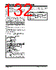
132 / 294 page  PIC16F631/677/685/687/689/690 DS41262D-page 130 © 2007 Microchip Technology Inc. 11.3 PWM Mode The PWM mode generates a Pulse-Width Modulated signal on the CCP1 pin. The duty cycle, period and resolution are determined by the following registers: •PR2 •T2CON • CCPR1L • CCP1CON In Pulse-Width Modulation (PWM) mode, the CCP module produces up to a 10-bit resolution PWM output on the CCP1 pin. Since the CCP1 pin is multiplexed with the PORT data latch, the TRIS for that pin must be cleared to enable the CCP1 pin output driver. Figure 11-3 shows a simplified block diagram of PWM operation. Figure 11-4 shows a typical waveform of the PWM signal. For a step-by-step procedure on how to set up the CCP module for PWM operation, see Section 11.3.7 “Setup for PWM Operation”. FIGURE 11-3: SIMPLIFIED PWM BLOCK DIAGRAM The PWM output (Figure 11-4) has a time base (period) and a time that the output stays high (duty cycle). FIGURE 11-4: CCP PWM OUTPUT Note: Clearing the CCP1CON register will relinquish CCP1 control of the CCP1 pin. CCPR1L CCPR1H(2) (Slave) Comparator TMR2 PR2 (1) RQ S Duty Cycle Registers CCP1CON<5:4> Clear Timer2, toggle CCP1 pin and latch duty cycle Note 1: The 8-bit timer TMR2 register is concatenated with the 2-bit internal system clock (FOSC), or 2 bits of the prescaler, to create the 10-bit time base. 2: In PWM mode, CCPR1H is a read-only register. TRIS CCP1 Comparator Period Pulse Width TMR2 = 0 TMR2 = CCPR1L:CCP1CON<5:4> TMR2 = PR2 |
|
ссылки URL |
| Вашему бизинису помогли Аллдатащит? [ DONATE ] |
Что такое Аллдатащит | реклама | контакт | Конфиденциальность | Ссылка на техническое описание | обмен ссыками | поиск по производителю All Rights Reserved©Alldatasheet.com |
| Russian : Alldatasheetru.com | Korean : Alldatasheet.co.kr | Spanish : Alldatasheet.es | French : Alldatasheet.fr | Italian : Alldatasheetit.com Portuguese : Alldatasheetpt.com | Polish : Alldatasheet.pl | Vietnamese : Alldatasheet.vn Indian : Alldatasheet.in | Mexican : Alldatasheet.com.mx | British : Alldatasheet.co.uk | New Zealand : Alldatasheet.co.nz |
|
Family Site : ic2ic.com |
icmetro.com |
 Russian ▼
 English
 Chinese
 German
 Japanese
 Russian
 Korean
 Spanish
 French
 Italian
 Portuguese
 Polish
 Vietnamese
 Indian
 Mexican
 British
 New Zealand