|
поискавой системы для электроныых деталей |
|
|
поискавой системы для электроныых деталей |
|
PIC16F631 датащи(PDF) 129 Page - Microchip Technology |
|
|
|||||||||||||||||||||||||||||
PIC16F631 датащи(HTML) 129 Page - Microchip Technology |
|
|
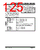
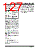
129 / 294 page  © 2007 Microchip Technology Inc. DS41262D-page 127 PIC16F631/677/685/687/689/690 11.0 ENHANCED CAPTURE/COMPARE/PWM MODULE The Enhanced Capture/Compare/PWM module is a peripheral which allows the user to time and control different events. In Capture mode, the peripheral allows the timing of the duration of an event. The Compare mode allows the user to trigger an external event when a predetermined amount of time has expired. The PWM mode can generate a Pulse-Width Modulated signal of varying frequency and duty cycle. Table 11-1 shows the timer resources required by the ECCP module. TABLE 11-1: ECCP MODE – TIMER RESOURCES REQUIRED ECCP Mode Timer Resource Capture Timer1 Compare Timer1 PWM Timer2 REGISTER 11-1: CCP1CON: ENHANCED CCP1 CONTROL REGISTER R/W-0 R/W-0 R/W-0 R/W-0 R/W-0 R/W-0 R/W-0 R/W-0 P1M1 P1M0 DC1B1 DC1B0 CCP1M3 CCP1M2 CCP1M1 CCP1M0 bit 7 bit 0 Legend: R = Readable bit W = Writable bit U = Unimplemented bit, read as ‘0’ -n = Value at POR ‘1’ = Bit is set ‘0’ = Bit is cleared x = Bit is unknown bit 7-6 P1M<1:0>: PWM Output Configuration bits If CCP1M<3:2> = 00, 01, 10: xx = P1A assigned as Capture/Compare input; P1B, P1C, P1D assigned as port pins If CCP1M<3:2> = 11: 00 = Single output; P1A modulated; P1B, P1C, P1D assigned as port pins 01 = Full-Bridge output forward; P1D modulated; P1A active; P1B, P1C inactive 10 = Half-Bridge output; P1A, P1B modulated with dead-band control; P1C, P1D assigned as port pins 11 = Full-Bridge output reverse; P1B modulated; P1C active; P1A, P1D inactive bit 5-4 DC1B<1:0>: PWM Duty Cycle Least Significant bits Capture mode: Unused. Compare mode: Unused. PWM mode: These bits are the two LSbs of the PWM duty cycle. The eight MSbs are found in CCPR1L. bit 3-0 CCP1M<3:0>: ECCP Mode Select bits 0000 = Capture/Compare/PWM off (resets ECCP module) 0001 = Unused (reserved) 0010 = Compare mode, toggle output on match (CCP1IF bit is set) 0011 = Unused (reserved) 0100 = Capture mode, every falling edge 0101 = Capture mode, every rising edge 0110 = Capture mode, every 4th rising edge 0111 = Capture mode, every 16th rising edge 1000 = Compare mode, set output on match (CCP1IF bit is set) 1001 = Compare mode, clear output on match (CCP1IF bit is set) 1010 = Compare mode, generate software interrupt on match (CCP1IF bit is set, CCP1 pin is unaffected) 1011 = Compare mode, trigger special event (CCP1IF bit is set; CCP1 resets TMR1 or TMR2, and starts an A/D conversion, if the ADC module is enabled) 1100 = PWM mode; P1A, P1C active-high; P1B, P1D active-high 1101 = PWM mode; P1A, P1C active-high; P1B, P1D active-low 1110 = PWM mode; P1A, P1C active-low; P1B, P1D active-high 1111 = PWM mode; P1A, P1C active-low; P1B, P1D active-low |
|
ссылки URL |
| Вашему бизинису помогли Аллдатащит? [ DONATE ] |
Что такое Аллдатащит | реклама | контакт | Конфиденциальность | Ссылка на техническое описание | обмен ссыками | поиск по производителю All Rights Reserved©Alldatasheet.com |
| Russian : Alldatasheetru.com | Korean : Alldatasheet.co.kr | Spanish : Alldatasheet.es | French : Alldatasheet.fr | Italian : Alldatasheetit.com Portuguese : Alldatasheetpt.com | Polish : Alldatasheet.pl | Vietnamese : Alldatasheet.vn Indian : Alldatasheet.in | Mexican : Alldatasheet.com.mx | British : Alldatasheet.co.uk | New Zealand : Alldatasheet.co.nz |
|
Family Site : ic2ic.com |
icmetro.com |
 Russian ▼
 English
 Chinese
 German
 Japanese
 Russian
 Korean
 Spanish
 French
 Italian
 Portuguese
 Polish
 Vietnamese
 Indian
 Mexican
 British
 New Zealand