|
поискавой системы для электроныых деталей |
|
|
поискавой системы для электроныых деталей |
|
SSL4120T датащи(PDF) 21 Page - NXP Semiconductors |
|
|
|||||||||||||||||||||||||||||
SSL4120T датащи(HTML) 21 Page - NXP Semiconductors |
|
|
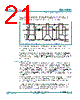
21 / 47 page  SSL4120T All information provided in this document is subject to legal disclaimers. © NXP B.V. 2012. All rights reserved. Objective data sheet Rev. 1 — 21 June 2012 21 of 47 NXP Semiconductors SSL4120T Resonant power supply control IC with PFC on. In this way the non-overlap time is optimized automatically, minimizing switching losses, even if the HB transition cannot be fully completed. Figure 10 illustrates the operation of the adaptive non-overlap time function in Inductive mode. The non-overlap time depends on the HB slope, but has upper and lower limits. An integrated minimum non-overlap time, tno(min), prevents cross conduction occurring under any circumstances. The maximum non-overlap time is limited to the oscillator charge time. If the HB slope lasts longer than the oscillator charge time (= 1⁄4 of HB switching period) the MOSFET is forced to switch on. In this case the MOSFET is not soft switching. This limitation ensures that, at very high switching frequencies, the MOSFET on-time is at least 1⁄4 of the HB switching period. 7.8.4.2 Capacitive mode The description above holds for normal operation with a switching frequency above the resonance frequency. When an error condition occurs (e.g. output short, load pulse too high) the switching frequency can be lower than the resonance frequency. The resonant tank then has a capacitive impedance. In Capacitive mode, the HB slope does not start after the MOSFET has switched off. Switching on the other MOSFET is not recommended in this situation. The absence of soft switching increases dissipation in the MOSFETs. In Capacitive mode, the body diode in the switched-off MOSFET may start conducting. Switching on the other MOSFET at this instant can result in the immediate destruction of the MOSFETs. The advanced adaptive non-overlap time of the SSL4120T will always wait until the slope at the half-bridge node starts. It guarantees safe switching of the MOSFETs in all circumstances. Figure 11 illustrates the operation of the adaptive non-overlap time function in Capacitive mode. In Capacitive mode, half the resonance period may elapse before the resonant current changes back to the correct polarity and starts charging the half-bridge node. The oscillator is slowed down until the half-bridge slope starts to allow this relatively long waiting time. See Section 7.8.5 for more details on the oscillator. Fig 10. Adaptive non-overlap time function (normal inductive operation) fast HB slope VBoost HB GATELS GATEHS 0 slow HB slope incomplete HB slope t 014aaa858 |
|
ссылки URL |
| Вашему бизинису помогли Аллдатащит? [ DONATE ] |
Что такое Аллдатащит | реклама | контакт | Конфиденциальность | Ссылка на техническое описание | обмен ссыками | поиск по производителю All Rights Reserved©Alldatasheet.com |
| Russian : Alldatasheetru.com | Korean : Alldatasheet.co.kr | Spanish : Alldatasheet.es | French : Alldatasheet.fr | Italian : Alldatasheetit.com Portuguese : Alldatasheetpt.com | Polish : Alldatasheet.pl | Vietnamese : Alldatasheet.vn Indian : Alldatasheet.in | Mexican : Alldatasheet.com.mx | British : Alldatasheet.co.uk | New Zealand : Alldatasheet.co.nz |
|
Family Site : ic2ic.com |
icmetro.com |
 Russian ▼
 English
 Chinese
 German
 Japanese
 Russian
 Korean
 Spanish
 French
 Italian
 Portuguese
 Polish
 Vietnamese
 Indian
 Mexican
 British
 New Zealand