|
поискавой системы для электроныых деталей |
|
|
поискавой системы для электроныых деталей |
|
IR3840WM датащи(PDF) 4 Page - International Rectifier |
|
|
|||||||||||||||||||||||||||||
IR3840WM датащи(HTML) 4 Page - International Rectifier |
|
|
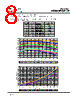
4 / 34 page  Rev 12.0 PD-97657 IR3840WMPbF 4 Pin Description Pin Name Description 1 Seq Sequence pin. Use two external resistors to set Simultaneous Power up sequencing. If this pin is not used connect to Vcc. 2 Fb Inverting input to the error amplifier. This pin is connected directly to the output of the regulator via resistor divider to set the output voltage and provide feedback to the error amplifier. 3 Comp Output of error amplifier. An external resistor and capacitor network is typically connected from this pin to Fb pin to provide loop compensation. 4 Gnd Signal ground for internal reference and control circuitry. 5 Rt Set the switching frequency. Connect an external resistor from this pin to Gnd to set the switching frequency. 6 SS/SD ¯¯ Soft start / shutdown. This pin provides user programmable soft-start function. Connect an external capacitor from this pin to Gnd to set the start up time of the output voltage. The converter can be shutdown by pulling this pin below 0.3V. 7 OCSet Current limit set point. A resistor from this pin to SW pin will set the current limit threshold. 8 PGood Power Good status pin. Output is open drain. Connect a pull up resistor from this pin to Vcc. If unused, it can be left open. 9 V CC This pin powers the internal IC and the drivers. A minimum of 1uF high frequency capacitor must be connected from this pin to the power ground (PGnd). 10 PGnd Power Ground. This pin serves as a separated ground for the MOSFET drivers and should be connected to the system’s power ground plane. 11 SW Switch node. This pin is connected to the output inductor. 12 V IN Input voltage connection pin. 13 Boot Supply voltage for high side driver. A 0.1uF capacitor must be connected from this pin to SW. 14 Enable Enable pin to turn on and off the device. Use two external resistors to set the turn on threshold (see Enable section). Connect this pin to Vcc if it is not used. 15 Gnd Signal ground for internal reference and control circuitry. |
|
ссылки URL |
| Вашему бизинису помогли Аллдатащит? [ DONATE ] |
Что такое Аллдатащит | реклама | контакт | Конфиденциальность | Ссылка на техническое описание | обмен ссыками | поиск по производителю All Rights Reserved©Alldatasheet.com |
| Russian : Alldatasheetru.com | Korean : Alldatasheet.co.kr | Spanish : Alldatasheet.es | French : Alldatasheet.fr | Italian : Alldatasheetit.com Portuguese : Alldatasheetpt.com | Polish : Alldatasheet.pl | Vietnamese : Alldatasheet.vn Indian : Alldatasheet.in | Mexican : Alldatasheet.com.mx | British : Alldatasheet.co.uk | New Zealand : Alldatasheet.co.nz |
|
Family Site : ic2ic.com |
icmetro.com |
 Russian ▼
 English
 Chinese
 German
 Japanese
 Russian
 Korean
 Spanish
 French
 Italian
 Portuguese
 Polish
 Vietnamese
 Indian
 Mexican
 British
 New Zealand