|
поискавой системы для электроныых деталей |
|
|
поискавой системы для электроныых деталей |
|
TDA7566 датащи(PDF) 16 Page - STMicroelectronics |
|
|
|||||||||||||||||||||||||||||
TDA7566 датащи(HTML) 16 Page - STMicroelectronics |
|
|
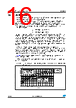
16 / 29 page  Diagnostics functional description TDA7566 16/29 Doc ID 9801 Rev 6 4.4 AC diagnostic It is targeted at detecting accidental disconnection of tweeters in 2-way speaker and, more in general, presence of capacitive (AC) coupled loads. This diagnostic is based on the notion that the overall speaker's impedance (woofer + parallel tweeter) will tend to increase towards high frequencies if the tweeter gets disconnected, because the remaining speaker (woofer) would be out of its operating range (high impedance). The diagnostic decision is made according to peak output current thresholds, as follows: Iout > 500mApk = normal status Iout < 250mApk = open tweeter To correctly implement this feature, it is necessary to briefly provide a signal tone (with the amplifier in "play") whose frequency and magnitude are such to determine an output current higher than 500mApk in normal conditions and lower than 250mApk should the parallel tweeter be missing. The test has to last for a minimum number of 3 sine cycles starting from the activation of the AC diagnostic function IB2<D2>) up to the I2C reading of the results (measuring period). To confirm presence of tweeter, it is necessary to find at least 3 current pulses over 500mA over all the measuring period, else an "open tweeter" message will be issued. The frequency / magnitude setting of the test tone depends on the impedance characteristics of each specific speaker being used, with or without the tweeter connected (to be calculated case by case). High-frequency tones (> 10 KHz) or even ultrasonic signals are recommended for their negligible acoustic impact and also to maximize the impedance module's ratio between with tweeter-on and tweeter-off. Figure 24 shows the Load Impedance as a function of the peak output voltage and the relevant diagnostic fields. This feature is disabled if any overloads leading to activation of the short-circuit protection occurs in the process. Figure 24. Current detection: load impedance magnitude |Z| vs. output peak voltage of the sinus 1 2 34 5 6 78 1 2 3 5 10 20 30 50 Vout (Peak) Load |z| (Ohm) Iout (peak) <250mA Iout (peak) >500mA Low current detection area (Open load) D5 = 1 of the DBx byres High current detection area (Normal load) D5 = 0 of the DBx bytes |
|
ссылки URL |
| Вашему бизинису помогли Аллдатащит? [ DONATE ] |
Что такое Аллдатащит | реклама | контакт | Конфиденциальность | Ссылка на техническое описание | обмен ссыками | поиск по производителю All Rights Reserved©Alldatasheet.com |
| Russian : Alldatasheetru.com | Korean : Alldatasheet.co.kr | Spanish : Alldatasheet.es | French : Alldatasheet.fr | Italian : Alldatasheetit.com Portuguese : Alldatasheetpt.com | Polish : Alldatasheet.pl | Vietnamese : Alldatasheet.vn Indian : Alldatasheet.in | Mexican : Alldatasheet.com.mx | British : Alldatasheet.co.uk | New Zealand : Alldatasheet.co.nz |
|
Family Site : ic2ic.com |
icmetro.com |
 Russian ▼
 English
 Chinese
 German
 Japanese
 Russian
 Korean
 Spanish
 French
 Italian
 Portuguese
 Polish
 Vietnamese
 Indian
 Mexican
 British
 New Zealand