|
поискавой системы для электроныых деталей |
|
|
поискавой системы для электроныых деталей |
|
TDA7566 датащи(PDF) 12 Page - STMicroelectronics |
|
|
|||||||||||||||||||||||||||||
TDA7566 датащи(HTML) 12 Page - STMicroelectronics |
|
|
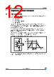
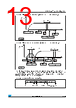
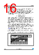
12 / 29 page  Diagnostics functional description TDA7566 12/29 Doc ID 9801 Rev 6 4 Diagnostics functional description 4.1 Turn-on diagnostic It is activated at the turn-on (standby out) under I2C bus request. Detectable output faults are: – Short to GND –Short to VS – Short across the speaker – Open speaker To verify if any of the above misconnections are in place, a subsonic (inaudible) current pulse (Figure 16) is internally generated, sent through the speaker(s) and sunk back.The Turn On diagnostic status is internally stored until a successive diagnostic pulse is requested (after a I2C reading). If the "standby out" and "diag. enable" commands are both given through a single programming step, the pulse takes place first (power stage still in standby mode, low, outputs = high impedance). Afterwards, when the Amplifier is biased, the PERMANENT diagnostic takes place. The previous Turn On state is kept until a short appears at the outputs. Figure 16. Turn-on diagnostic: working principle Figure 17 and 18 show SVR and output waveforms at the turn-on (standby out) with and without Turn-on diagnostic. CH- CH+ Isource Vs~5V Isink t (ms) I (mA) Isink Isource ~100ms Measure time |
|
ссылки URL |
| Вашему бизинису помогли Аллдатащит? [ DONATE ] |
Что такое Аллдатащит | реклама | контакт | Конфиденциальность | Ссылка на техническое описание | обмен ссыками | поиск по производителю All Rights Reserved©Alldatasheet.com |
| Russian : Alldatasheetru.com | Korean : Alldatasheet.co.kr | Spanish : Alldatasheet.es | French : Alldatasheet.fr | Italian : Alldatasheetit.com Portuguese : Alldatasheetpt.com | Polish : Alldatasheet.pl | Vietnamese : Alldatasheet.vn Indian : Alldatasheet.in | Mexican : Alldatasheet.com.mx | British : Alldatasheet.co.uk | New Zealand : Alldatasheet.co.nz |
|
Family Site : ic2ic.com |
icmetro.com |
 Russian ▼
 English
 Chinese
 German
 Japanese
 Russian
 Korean
 Spanish
 French
 Italian
 Portuguese
 Polish
 Vietnamese
 Indian
 Mexican
 British
 New Zealand