|
поискавой системы для электроныых деталей |
|
|
поискавой системы для электроныых деталей |
|
PIC16F631 датащи(PDF) 232 Page - Microchip Technology |
|
|
|||||||||||||||||||||||||||||
PIC16F631 датащи(HTML) 232 Page - Microchip Technology |
|
|
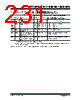
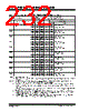
232 / 294 page  PIC16F631/677/685/687/689/690 DS41262D-page 230 © 2007 Microchip Technology Inc. 17.2 DC Characteristics: PIC16F631/677/685/687/689/690-I (Industrial) DC CHARACTERISTICS Standard Operating Conditions (unless otherwise stated) Operating temperature -40 °C ≤ TA ≤ +85°C for industrial Param No. Device Characteristics Min Typ† Max Units Conditions VDD Note D010 Supply Current (IDD)(1, 2) —9 TBD μA2.0 FOSC = 32 kHz LP Oscillator mode —18 TBD μA3.0 —35 TBD μA5.0 D011* — 140 240 μA2.0 FOSC = 1 MHz XT Oscillator mode — 220 380 μA3.0 — 380 550 μA5.0 D012 — 260 360 μA2.0 FOSC = 4 MHz XT Oscillator mode — 420 650 μA3.0 —0.8 1.1 mA 5.0 D013* — 130 220 μA2.0 FOSC = 1 MHz EC Oscillator mode — 215 360 μA3.0 — 360 520 μA5.0 D014 — 220 340 μA2.0 FOSC = 4 MHz EC Oscillator mode — 375 550 μA3.0 —0.65 1.0 mA 5.0 D015 — 8 20 μA2.0 FOSC = 31 kHz LFINTOSC mode —16 40 μA3.0 —31 65 μA5.0 D016* — 340 450 μA2.0 FOSC = 4 MHz HFINTOSC mode — 500 700 μA3.0 —0.8 1.2 mA 5.0 D017 — 410 650 μA2.0 FOSC = 8 MHz HFINTOSC mode — 700 950 μA3.0 — 1.30 1.65 mA 5.0 D018 — 230 400 μA2.0 FOSC = 4 MHz EXTRC mode(3) — 400 680 μA3.0 —0.63 1.1 mA 5.0 D019 — 2.6 3.25 mA 4.5 FOSC = 20 MHz HS Oscillator mode — 2.8 3.35 mA 5.0 Legend: TBD = To Be Determined † Data in “Typ” column is at 5.0V, 25 °C unless otherwise stated. These parameters are for design guidance only and are not tested. Note 1: The test conditions for all IDD measurements in Active Operation mode are: OSC1 = external square wave, from rail-to-rail; all I/O pins tri-stated, pulled to VDD; MCLR = VDD; WDT disabled. 2: The supply current is mainly a function of the operating voltage and frequency. Other factors, such as I/O pin loading and switching rate, oscillator type, internal code execution pattern and temperature, also have an impact on the current consumption. 3: For RC oscillator configurations, current through REXT is not included. The current through the resistor can be extended by the formula IR = VDD/2REXT (mA) with REXT in k Ω. 4: The peripheral current is the sum of the base IDD or IPD and the additional current consumed when this peripheral is enabled. The peripheral Δ current can be determined by subtracting the base IDD or IPD current from this limit. Max values should be used when calculating total current consumption. 5: The power-down current in Sleep mode does not depend on the oscillator type. Power-down current is measured with the part in Sleep mode, with all I/O pins in high-impedance state and tied to VDD. |
|
ссылки URL |
| Вашему бизинису помогли Аллдатащит? [ DONATE ] |
Что такое Аллдатащит | реклама | контакт | Конфиденциальность | Ссылка на техническое описание | обмен ссыками | поиск по производителю All Rights Reserved©Alldatasheet.com |
| Russian : Alldatasheetru.com | Korean : Alldatasheet.co.kr | Spanish : Alldatasheet.es | French : Alldatasheet.fr | Italian : Alldatasheetit.com Portuguese : Alldatasheetpt.com | Polish : Alldatasheet.pl | Vietnamese : Alldatasheet.vn Indian : Alldatasheet.in | Mexican : Alldatasheet.com.mx | British : Alldatasheet.co.uk | New Zealand : Alldatasheet.co.nz |
|
Family Site : ic2ic.com |
icmetro.com |
 Russian ▼
 English
 Chinese
 German
 Japanese
 Russian
 Korean
 Spanish
 French
 Italian
 Portuguese
 Polish
 Vietnamese
 Indian
 Mexican
 British
 New Zealand