 |
поискавой системы для электроныых деталей |
|
|
поискавой системы для электроныых деталей |
|
The question interval is too short.
Please try again in a few seconds.

Hello, Please ask a question about PIC16F684 Datasheet
# Example questions:
➢ Explain how the rp0 bit affects data memory access in the pic16f684.
➢ What is the purpose of the pclath register?
➢ Describe the function of the status register and identify two of its important bits.
| Part No. | PIC16F684 |
| Manufacturer | MICROCHIP |
| Size | 3Mb |
| Pages | 192 pages |
| Description | 14-Pin, Flash-Based 8-Bit CMOS Microcontrollers |


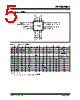


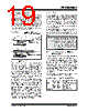




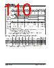
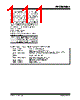


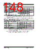


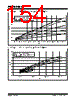


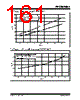




This is a very comprehensive excerpt from a PIC microcontroller datasheet. Here's a breakdown and explanation of what's presented, along with why it's important for understanding how to program this microcontroller.
Overall Purpose:
This section of the datasheet (specifically, Memory Organization and Special Function Registers) details the architecture of the PIC16F684's memory and the registers used to control its various functions. It’s absolutely critical for anyone writing code for this microcontroller.
1. Program Memory Organization (Section 2.1):
️· Program Counter (PC): The PC points to the next instruction to be executed. It's 13 bits wide, meaning it can theoretically address 8192 (2<sup>13</sup>) locations in program memory.
️· Limited Implementation: However, only the first 2048 (0000h - 07FFh) locations are physically implemented in the PIC16F684. Attempting to execute instructions beyond this range will cause the program counter to "wrap around," reusing the same 2048 locations.
️· Reset and Interrupt Vectors:
- Reset Vector (0000h): This is the address the microcontroller jumps to when it powers up or resets. Your startup code usually resides here.
- Interrupt Vector (0004h): This is the starting point for the interrupt routine. When an interrupt occurs, the program execution jumps to this address to handle the interrupt.
2. Data Memory Organization (Section 2.2):
️· File Select Register (FSR): This is a key concept for indirect addressing. The FSR holds an address. The `INDF` (Indirect File) register doesn't exist as a physical register; instead, it operates *indirectly*. When the CPU attempts to read or write to `INDF`, it uses the value in the FSR to access the data memory location.
️· Bank Switching: PIC microcontrollers often use a "bank switching" scheme. The PIC16F684 has two banks (Bank 0 and Bank 1). The RP0 (Register Bank Select) bit in the `STATUS` register determines which bank is active. This is useful when you have more registers than can fit within a single bank.
️· General Purpose Registers (GPR): These are the registers you directly use in your code for storing and manipulating data.
️· Special Function Registers (SFR): These registers control the peripherals (timers, ADC, UART, etc.) and the core functionality of the microcontroller.
3. Special Function Register Table (Table 2-1):
This is a summary of the important SFRs, including their addresses and bit descriptions. Let's break down the columns:
️· Addr: The memory address of the register.
️· Name: The name of the register (e.g., `INDF`, `STATUS`, `TMR0`).
️· Bit Descriptions: A description of what each bit within the register controls. You'll need to understand these bit meanings to correctly configure the microcontroller's peripherals and functions.
️· Value on POR/BOR: The initial value of the register after a Power-On Reset (POR) or Brown-Out Reset (BOR).
️· Page: This column cross-references the SFR's description to a section within the datasheet's description of the peripheral that manages that register.
Key Registers Highlighted:
️· INDF: Indirect File - Used for indirect addressing.
️· TMR0: Timer 0 Register – Used to configure and read the status of the Timer 0 module.
️· STATUS: This register holds status flags like Carry (C), Zero (Z), Digital Carry (DC), and Register Bank Select (RP0). It also contains bits for interrupt enablement.
️· FSR: File Select Register – Used in conjunction with `INDF` for indirect addressing.
️· PORTA & PORTC: These registers are used to control the digital input/output pins connected to the microcontroller's pins labeled "A" and "C".
️· PCL & PCLATH: Program Counter Low and High bytes. Used for accessing different code sections during program execution.
️· INTCON: Interrupt Control Register - This register controls the enabling and status of various interrupts.
️· PIR1: Peripheral Interrupt Register 1 - Indicates which peripherals have generated an interrupt.
️· TMR1L: Timer 1 Low Byte – the low byte of a 16-bit timer register.
Why This Information is Critical:
️· Understanding Memory Limits: Knowing the limitations of the program memory prevents code from wrapping and causing unpredictable behavior.
️· Bank Switching: Being able to switch between banks enables you to utilize the full range of available registers.
️· Peripheral Configuration: Understanding the SFRs is *essential* for configuring and using the microcontroller's peripherals (timers, ADCs, serial communication, etc.). Each bit in an SFR usually controls a specific function.
️· Interrupt Handling: Knowing how to manage interrupt vectors allows you to create responsive programs that react to external events.
This is a very comprehensive excerpt from a PIC microcontroller datasheet. Here's a breakdown and explanation of what's presented, along with why it's important for understanding how to program this microcontroller.
Overall Purpose:
This section of the datasheet (specifically, Memory Organization and Special Function Registers) details the architecture of the PIC16F684's memory and the registers used to control its various functions. It’s absolutely critical for anyone writing code for this microcontroller.
1. Program Memory Organization (Section 2.1):
️· Program Counter (PC): The PC points to the next instruction to be executed. It's 13 bits wide, meaning it can theoretically address 8192 (2<sup>13</sup>) locations in program memory.
️· Limited Implementation: However, only the first 2048 (0000h - 07FFh) locations are physically implemented in the PIC16F684. Attempting to execute instructions beyond this range will cause the program counter to "wrap around," reusing the same 2048 locations.
️· Reset and Interrupt Vectors:
- Reset Vector (0000h): This is the address the microcontroller jumps to when it powers up or resets. Your startup code usually resides here.
- Interrupt Vector (0004h): This is the starting point for the interrupt routine. When an interrupt occurs, the program execution jumps to this address to handle the interrupt.
2. Data Memory Organization (Section 2.2):
️· File Select Register (FSR): This is a key concept for indirect addressing. The FSR holds an address. The `INDF` (Indirect File) register doesn't exist as a physical register; instead, it operates *indirectly*. When the CPU attempts to read or write to `INDF`, it uses the value in the FSR to access the data memory location.
️· Bank Switching: PIC microcontrollers often use a "bank switching" scheme. The PIC16F684 has two banks (Bank 0 and Bank 1). The RP0 (Register Bank Select) bit in the `STATUS` register determines which bank is active. This is useful when you have more registers than can fit within a single bank.
️· General Purpose Registers (GPR): These are the registers you directly use in your code for storing and manipulating data.
️· Special Function Registers (SFR): These registers control the peripherals (timers, ADC, UART, etc.) and the core functionality of the microcontroller.
3. Special Function Register Table (Table 2-1):
This is a summary of the important SFRs, including their addresses and bit descriptions. Let's break down the columns:
️· Addr: The memory address of the register.
️· Name: The name of the register (e.g., `INDF`, `STATUS`, `TMR0`).
️· Bit Descriptions: A description of what each bit within the register controls. You'll need to understand these bit meanings to correctly configure the microcontroller's peripherals and functions.
️· Value on POR/BOR: The initial value of the register after a Power-On Reset (POR) or Brown-Out Reset (BOR).
️· Page: This column cross-references the SFR's description to a section within the datasheet's description of the peripheral that manages that register.
Key Registers Highlighted:
️· INDF: Indirect File - Used for indirect addressing.
️· TMR0: Timer 0 Register – Used to configure and read the status of the Timer 0 module.
️· STATUS: This register holds status flags like Carry (C), Zero (Z), Digital Carry (DC), and Register Bank Select (RP0). It also contains bits for interrupt enablement.
️· FSR: File Select Register – Used in conjunction with `INDF` for indirect addressing.
️· PORTA & PORTC: These registers are used to control the digital input/output pins connected to the microcontroller's pins labeled "A" and "C".
️· PCL & PCLATH: Program Counter Low and High bytes. Used for accessing different code sections during program execution.
️· INTCON: Interrupt Control Register - This register controls the enabling and status of various interrupts.
️· PIR1: Peripheral Interrupt Register 1 - Indicates which peripherals have generated an interrupt.
️· TMR1L: Timer 1 Low Byte – the low byte of a 16-bit timer register.
Why This Information is Critical:
️· Understanding Memory Limits: Knowing the limitations of the program memory prevents code from wrapping and causing unpredictable behavior.
️· Bank Switching: Being able to switch between banks enables you to utilize the full range of available registers.
️· Peripheral Configuration: Understanding the SFRs is *essential* for configuring and using the microcontroller's peripherals (timers, ADCs, serial communication, etc.). Each bit in an SFR usually controls a specific function.
️· Interrupt Handling: Knowing how to manage interrupt vectors allows you to create responsive programs that react to external events.
| Part No. | PIC16F684 |
| Manufacturer | MICROCHIP |
| Size | 3Mb |
| Pages | 192 pages |
| Description | 14-Pin, Flash-Based 8-Bit CMOS Microcontrollers |
| Вашему бизинису помогли Аллдатащит? [ DONATE ] |
Что такое Аллдатащит | реклама | контакт | Конфиденциальность | Ссылка на техническое описание | обмен ссыками | поиск по производителю All Rights Reserved©Alldatasheet.com |
| Russian : Alldatasheetru.com | Korean : Alldatasheet.co.kr | Spanish : Alldatasheet.es | French : Alldatasheet.fr | Italian : Alldatasheetit.com Portuguese : Alldatasheetpt.com | Polish : Alldatasheet.pl | Vietnamese : Alldatasheet.vn Indian : Alldatasheet.in | Mexican : Alldatasheet.com.mx | British : Alldatasheet.co.uk | New Zealand : Alldatasheet.co.nz |
|
Family Site : ic2ic.com |
icmetro.com |
 Russian ▼
  English
 Chinese
 German
 Japanese
 Korean
 Spanish
 French
 Italian
 Portuguese
 Polish
 Vietnamese
 Indian
 Mexican
 British
 New Zealand