|
поискавой системы для электроныых деталей |
|
|
поискавой системы для электроныых деталей |
|
AUIR08152S датащи(PDF) 12 Page - Infineon Technologies AG |
|
|
|||||||||||||||||||||||||||||
AUIR08152S датащи(HTML) 12 Page - Infineon Technologies AG |
|
|
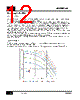
12 / 18 page  AUIR08152S 12 Rev. A8.0 2015-11-09 General Application Hints IN & LPM interface IN and LPM have a current capability of 10mA max (source and sink); these limits only apply in case the stage driving these signals may go above Vcc or below Vcc-40V. In the majority of cases, when the driving stage is only an open collector, referenced at GND or –Vee, when looking at the functional block diagram, it appears the internal comparators have 6V zener clamp diodes, whose current is limited to much lower current by internal limiting resistors. These currents are IIN15 and ILPM15 and are reported in the static electrical characteristics for Vcc=15V and IN and LPM being pulled down at GND level. In any case, when driving IN and LPM via open collector outputs, a pull-up resistor is needed, to guarantee clean rise times (fall time are uniquely determined by the speed the open collectors turns-on). Rise time is determined by the pull-up resistor and the equivalent pin capacitance to Vcc. Typically few hundred Ohm to few kOhm are placed here. If a push pull, and not an open collector, stage is used to drive IN and LPM, no pull-up resistor is needed but pay attention the push pull stage is fed between Vcc and GND or Vcc and –Vee. A pull down resistor (few hundred kOhm) is suggested instead, especially if long traces or cables connect the predriver to the buffer IC. IC power dissipation This figure is mostly related to the switching frequency, the value of external gate resistances, and the equivalent load capacitance (the IGBT gate Ciss). A complete characterization of the IC capabilities is given in figure 6, and shown here again for sake of clarity. |
|
|
ссылки URL |
| Вашему бизинису помогли Аллдатащит? [ DONATE ] |
Что такое Аллдатащит | реклама | контакт | Конфиденциальность | Ссылка на техническое описание | обмен ссыками | поиск по производителю All Rights Reserved©Alldatasheet.com |
| Russian : Alldatasheetru.com | Korean : Alldatasheet.co.kr | Spanish : Alldatasheet.es | French : Alldatasheet.fr | Italian : Alldatasheetit.com Portuguese : Alldatasheetpt.com | Polish : Alldatasheet.pl | Vietnamese : Alldatasheet.vn Indian : Alldatasheet.in | Mexican : Alldatasheet.com.mx | British : Alldatasheet.co.uk | New Zealand : Alldatasheet.co.nz |
|
Family Site : ic2ic.com |
icmetro.com |
 Russian ▼
 English
 Chinese
 German
 Japanese
 Russian
 Korean
 Spanish
 French
 Italian
 Portuguese
 Polish
 Vietnamese
 Indian
 Mexican
 British
 New Zealand