|
поискавой системы для электроныых деталей |
|
|
поискавой системы для электроныых деталей |
|
LTC3490 датащи(PDF) 7 Page - Linear Technology |
|
|
|||||||||||||||||||||||||||||
LTC3490 датащи(HTML) 7 Page - Linear Technology |
|
|
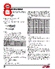
7 / 12 page  7 LTC3490 3490fa APPLICATIO S I FOR ATIO The LTC3490 requires only four external components to operate: an inductor, an output capacitor, a switch and a pull-down resistor. The inductor is nominally set at 3.3 µH and the capacitor at 4.7 µF. Optional components include an input capacitor and dimming resistors. COMPONENT SELECTION Inductor Selection The high frequency operation of the LTC3490 allows the use of small surface mount inductors. The minimum inductance value is proportional to the operating fre- quency and is limited by the following constraints: L f H and L VV V f Ripple V H IN MIN OUT MAX IN MIN OUT MAX ≥ ≥ () 3 () ( ) () () •– •• where: f = Operating Frequency (Hz) Ripple = Inductor Current Ripple (A) VIN(MIN) = Minimum Input Voltage (V) VOUT(MAX) = Maximum Output Voltage (V) The inductor current ripple is typically set to 20% to 40% of the inductor current. The peak inductor current is given by: II VI R R I VR I VV V Lf V LPK OUT OUT OUT P N IN IN N IN IN OUT IN OUT = + () + () •– • –• – •• • 2 where: VIN = Input Voltage (V) VOUT = Output Voltage (V) IOUT = LED Drive Current (A) IIN = Input Current = VOUT/VIN • IOUT (A) RP = RDSON of the PFET Switch (Ω) RN = RDSON of the NFET Switch (Ω) For high efficiency, choose an inductor with a high fre- quency core material, such as ferrite, to reduce core losses. The inductor should have low ESR (equivalent series resistance) to reduce the I2R losses and must be able to handle the peak inductor current at full load without saturating. In single cell applications, the inductor ESR must be below 25m Ω to keep the efficiency up and maintain output current regulation. Dual cell applications can tolerate significantly higher ESR (up to 75m Ω) with minimal efficiency degradation. Molded chokes or chip inductors usually do not have enough core to support the peak inductor currents in the 1A to 2A region. If radiated noise is an issue, use a toroid, pot core or shielded bobbin inductor to minimize radiated noise. See Table 1 for a list of suggested inductors. Look closely at the manufacturers data sheets; they specify saturation current differently. Table 1. Inductor Information INDUCTOR PART NUMBER ESR (m Ω) SATURATION CURRENT (A) TOKO A918CY-3R3M 47 1.97 TYCO DN4835-3R3M 58 2.15 TDK SLF7045T-3R3M2R5 20 2.5 Output Capacitor Selection The output capacitor value and equivalent series resis- tance (ESR) are the primary factors in the output ripple. The output ripple is not a direct concern for LED drive as the LED will operate at the average current value. However the peak pulsed forward current rating of the LED must not be exceeded to avoid damaging the LED. |
|
|
ссылки URL |
| Вашему бизинису помогли Аллдатащит? [ DONATE ] |
Что такое Аллдатащит | реклама | контакт | Конфиденциальность | Ссылка на техническое описание | обмен ссыками | поиск по производителю All Rights Reserved©Alldatasheet.com |
| Russian : Alldatasheetru.com | Korean : Alldatasheet.co.kr | Spanish : Alldatasheet.es | French : Alldatasheet.fr | Italian : Alldatasheetit.com Portuguese : Alldatasheetpt.com | Polish : Alldatasheet.pl | Vietnamese : Alldatasheet.vn Indian : Alldatasheet.in | Mexican : Alldatasheet.com.mx | British : Alldatasheet.co.uk | New Zealand : Alldatasheet.co.nz |
|
Family Site : ic2ic.com |
icmetro.com |
 Russian ▼
 English
 Chinese
 German
 Japanese
 Russian
 Korean
 Spanish
 French
 Italian
 Portuguese
 Polish
 Vietnamese
 Indian
 Mexican
 British
 New Zealand