|
поискавой системы для электроныых деталей |
|
|
поискавой системы для электроныых деталей |
|
DS1990 датащи(PDF) 6 Page - Dallas Semiconductor |
|
|
|||||||||||||||||||||||||||||
DS1990 датащи(HTML) 6 Page - Dallas Semiconductor |
|
|
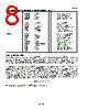
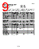
6 / 10 page  DS1990A 6 of 10 1-WIRE SIGNALING The DS1990A requires strict protocols to ensure data integrity. The protocol consists of four types of signaling on one line: Reset sequence with Reset Pulse and Presence Pulse, write 0, write 1 and read data. All these signals except presence pulse are initiated by the bus master. The initialization sequence required to begin any communication with the DS1990A is shown in Figure 5. A Reset Pulse followed by a Presence Pulse indicates the DS1990A is ready to send or receive data given the correct ROM command. The bus master transmits (TX ) a reset pulse ( a low signal for a minimum of 480 µs). The bus master then releases the line and goes into receive mode (RX ). The 1-Wire bus is pulled to a high state via the 5 k Ω pullup resistor. After detecting the rising edge on the data contact, the DS1990A waits (t PDH , 15-60 µs) and then transmits the presence pulse (t PDL , 60-240 µs). READ/WRITE TIME SLOTS The definitions of write and read time slots are illustrated in Figure 6. All time slots are initiated by the master driving the data line low. The falling edge of the data line synchronizes the DS1990A to the master by triggering a delay circuit in the DS1990A. During write time slots, the delay circuit determines when the DS1990A will sample the data line. For a read data time slot, if a “0” is to be transmitted, the delay circuit determines how long the DS1990A will hold the data line low overriding the 1 generated by the master. If the data bit is a “1”, the iButton will leave the read data time slot unchanged. INITIALIZATION PROCEDURE “RESET AND PRESENCE PULSES” Figure 5 480 µs ≤ t RSTL < ∞ * 480 µs ≤ t RSTH < ∞ (includes recovery time) 15 µs ≤ t PDH < 60 µs 60 µs ≤ t PDL < 240 µs ∗ In order not to mask interrupt signaling by other devices on the 1-Wire bus, t RSTL + tR should always be less than 960 µs. RESISTOR MASTER DS1990A |
|
|
ссылки URL |
| Вашему бизинису помогли Аллдатащит? [ DONATE ] |
Что такое Аллдатащит | реклама | контакт | Конфиденциальность | Ссылка на техническое описание | обмен ссыками | поиск по производителю All Rights Reserved©Alldatasheet.com |
| Russian : Alldatasheetru.com | Korean : Alldatasheet.co.kr | Spanish : Alldatasheet.es | French : Alldatasheet.fr | Italian : Alldatasheetit.com Portuguese : Alldatasheetpt.com | Polish : Alldatasheet.pl | Vietnamese : Alldatasheet.vn Indian : Alldatasheet.in | Mexican : Alldatasheet.com.mx | British : Alldatasheet.co.uk | New Zealand : Alldatasheet.co.nz |
|
Family Site : ic2ic.com |
icmetro.com |
 Russian ▼
 English
 Chinese
 German
 Japanese
 Russian
 Korean
 Spanish
 French
 Italian
 Portuguese
 Polish
 Vietnamese
 Indian
 Mexican
 British
 New Zealand